Pioneer AVH-P5200BT Installation Manual - Page 9
Installation - how to install a
 |
UPC - 012562975900
View all Pioneer AVH-P5200BT manuals
Add to My Manuals
Save this manual to your list of manuals |
Page 9 highlights
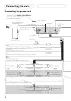
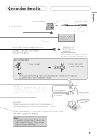
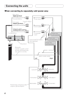
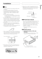
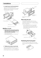
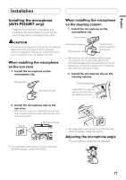
English Installation Note • Check all connections and systems before final installation. • Do not use unauthorized parts. The use of unauthorized parts may cause malfunctions. • Consult with your dealer if installation requires drilling of holes or other modifications of the vehicle. • Do not install this unit where: - it may interfere with operation of the vehicle. - it may cause injury to a passenger as a result of a sudden stop. • Do not install the display where it may (i) obstruct the driver's vision, (ii) impair the performance of any of the vehicle's operating systems or safety features, including air bags, hazard lamp buttons or (iii) impair the driver's ability to safely operate the vehicle. • The semiconductor laser will be damaged if it overheats. Install this unit away from hot places such as near the heater outlet. • Optimum performance is obtained when the unit is installed at an angle of less than 30°. • When installing, to ensure proper heat dispersal when using this unit, make sure you leave ample space behind the rear panel and wrap any loose cables so they are not blocking the vents. • Make sure you leave enough gap between the dashboard and the LCD panel of this unit so the LCD panel can be opened and closed without contacting with the dashboard. Dashboard Leave gap LCD panel DIN front/rear-mount This unit can be properly installed either from "Front" (conventional DIN Front-mount) or "Rear" (DIN Rear-mount installation, utilizing threaded screw holes at the sides of unit chassis). For details, refer to the following installation methods. • Use commercially available parts when installing. DIN Front-mount 1. Decide the position of the side brackets. • When installing in a shallow space, change the position of side brackets (small). Leave ample space Dashboard • The cords must not cover up the area shown in the figure below. This is necessary to allow the amplifires to radiate freely. Do not cover this area. Side bracket (small) Flush surface screw (5 mm × 6 mm) 9
-
 1
1 -
2
-
3
-
 4
4 -
 5
5 -
 6
6 -
 7
7 -
 8
8 -
 9
9 -
 10
10 -
 11
11 -
 12
12 -
 13
13 -
 14
14 -
15
-
16
-
17
-
18
-
19
-
20
-
21
-
22
-
23
-
24
-
25
-
26
-
27
-
28
-
29
-
30
-
31
-
32
 |
 |
