Pioneer DEH-P77DH Other Manual - Page 14
STARTER CUT-OFF Blue/Brown
 |
UPC - 012562500638
View all Pioneer DEH-P77DH manuals
Add to My Manuals
Save this manual to your list of manuals |
Page 14 highlights
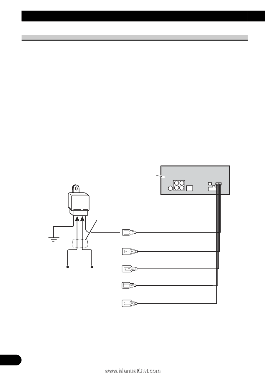
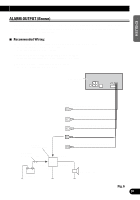
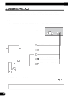
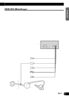
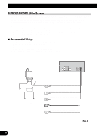
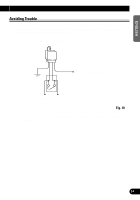
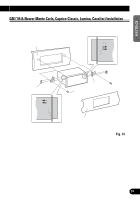
DFS Alarm Installation STARTER CUT-OFF (Blue/Brown) The blue/brown lead will provide a continuous +12 V output while alarm is sounding and for 30 minutes after initial trigger, up to 5 consecutive triggers. This lead has a maximum current capability of 500 mA and can be used to trigger a relay to disable the starter. Note: • In order for the "DFS Alarm" to operate when a window is broken, connect this unit's White/Red (ALARM SENSOR) lead to glass sensor securely. • In order for the "DFS Alarm" to operate when a door is forced open, connect this unit's White/Yellow (DOOR SWITCH) lead securely. 7 Recommended Wiring: 30 amp relay (sold separately) required to disable starter. • Connect blue/brown lead to one side of relay coil. • Connect other side of coil to ground. • Locate starter wire under dash, near steering column. • Cut starter wire and try to start vehicle to verify wire is correct. • Connect key side of cut wire to normally closed pin. • Connect starter side of cut wire to common pin. 30 A "SPDT" RELAY (sold separately) This product See the "Avoiding Trouble". Blue/Brown White/Orange (refer to "DOOR LOCK".) To Starter From Ignition Switch White/Red (refer to "ALARM SENSOR".) Brown (refer to "ALARM OUTPUT".) White/Yellow (refer to "DOOR SWITCH".) Fig. 9 13
-
 1
1 -
2
-
3
-
4
-
5
-
6
-
7
-
8
-
 9
9 -
 10
10 -
 11
11 -
 12
12 -
 13
13 -
 14
14 -
 15
15 -
 16
16 -
 17
17 -
 18
18 -
 19
19 -
20
-
21
-
22
-
23
-
24
-
25
-
26
-
27
-
28
-
29
-
30
-
31
-
32
-
33
-
34
-
35
-
36
-
37
-
38
-
39
-
40
-
41
-
42
-
43
-
44
-
45
-
46
-
47
-
48
 |
 |