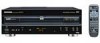
Pioneer DVL-909 Service Guide - Page 12
Dv-505, Dvl-909, Dv-s9, 2 Dirb Block Dirb Assy, Dv-s9 Only, 3 96k, 24-bit, Hibit Legato S, System - generations
 |
View all Pioneer DVL-909 manuals
Add to My Manuals
Save this manual to your list of manuals |
Page 12 highlights
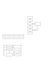
DV-505, DVL-909, DV-S9 2.2 DIRB BLOCK (DIRB ASSY) 2.3 96K, 24-Bit, HIBIT LEGATO S (DV-S9 ONLY) SYSTEM (AUDIO ASSY) The two major purposes of the DIRB block are the following: (1) Switching between data reproduced from a disc and a data signal in DAC mode (2) Data decoding in external input mode (DAC mode) (1) Switching Between Data Reproduced from a Disc and a Data Signal in DAC Mode The signal switching is performed at IC811, sending 3-line data (LRCK, BCK and DATA) to the AUDIO Assy. The switching control line (DAC MODE) is supplied from the DVD MAIN Assy. The master clock (MCK) is generated by a crystal on the AUDIO Assy when reproducing a disc, and by IC861 in DAC mode. MCK is sent to the AUDIO Assy via RXP. (2) Data Decoding in External Input Mode (DAC All 16-bit and 20-bit sources are converted to 24-bit data by IC101, which lets a 24-bit data pass through. As PCM1702P is a 20-bit D/A converter, processing of the upper 20 bits is assigned to it by the shift register. The lower 4 bits are converted from serial to parallel, then the significance of each bit is converted digital to analog, functioning as a 4-bit D/A converter for the lower 4 bits. By adding the lower 4 bits to the upper 20 bits in the low-pass & ADD block, D/A conversion is achieved for 24 bits. Hi Bit IC101 Legato S IC111 Mode) When the user selects DAC mode, the DAC MODE port is set to H and VCO in IC861 starts oscillating. (VCO does not oscillate in any other modes than DAC mode.) When there is a toss link of an external input or a coaxial digital input, the digital input signal is sent to IC861 from RXP of CN801, generating 3-line data corresponding to the input sampling frequency. At the same time, the master clock (MCK) to be used in DAC mode is also generated. For a 96kHz input, the MCK frequency is divided by 2 by IC831. When the user selects the internal clock as the system clock, the clock generated by the crystal on the AUDIO Assy is sent to the DVD MAIN Assy. When the user selects an external sync as the system clock, the following parameters are used. Shift Register TC74HC164AF D/A Converter PCM1702P Low-pass & ADD Analog Output Serial to Parallel and Significance Conversion TC74HC163AF FS(kHz) 32 44.1 48 96 16M clock in 18M clock in the AUDIO Assy the AUDIO Assy Oscillates Oscillates Stops oscillating Oscillates Oscillates Stops oscillating Oscillates Stops oscillating 16M clock sent to 18M clock sent to the DVD MAIN Assy the DVD MAIN Assy Crystal 16M clock Crystal 18M clock DIR 16M clock Crystal 18M clock Crystal 16M clock DIR 18M clock Crystal 16M clock DIR 18M clock If there is no external input or locking onto the input digital signal cannot be achieved, the ERR signal at pin 43 of IC861 is set to H, and the crystal in the AUDIO Assy immediately starts oscillating. In such cases, the clock sent to the DVD MAIN Assy will always be a crystal clock. IC901 16M Selector IC902 18M Selector IC811 Data Selector CN801 IC861 DIR IC831 Clock Selector IC835 1/2 Divider CN811 12
-
 1
1 -
2
-
3
-
4
-
5
-
6
-
 7
7 -
 8
8 -
 9
9 -
 10
10 -
 11
11 -
 12
12 -
 13
13 -
 14
14 -
 15
15 -
 16
16 -
 17
17 -
18
-
19
-
20
-
21
-
22
-
23
-
24
-
25
-
26
-
27
-
28
-
29
-
30
-
31
-
32
-
33
-
34
-
35
-
36
-
37
-
38
-
39
-
40
-
41
-
42
-
43
-
44
-
45
-
46
-
47
 |
 |
