Pioneer DVL-909 Service Guide - Page 19
Dv-505, Dvl-909, Dv-s9, Descriptions Of New Func, Tions In Test Mode - problems
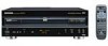 |
View all Pioneer DVL-909 manuals
Add to My Manuals
Save this manual to your list of manuals |
Page 19 highlights
DV-505, DVL-909, DV-S9 (20) Revision of the DVD mechanism controller [M Revision number of the external ROM part (flash ROM) of the DVD mechanism controller Revision of the internal ROM (core part) of the DVD mechanism controller (21) Revision of the CLD mechanism controller [L (22) Version of the AV-1 chip [AV:∗.∗] (23) Version of the FL controller [F:∗.∗] (24) Control number of the GUI-ROM [GUI:∗∗∗] (25) The part number of the flash ROM and system controller [S Part number of the flash ROM (Example) VYW1536-A → W1536A (Example) PD626A9 → 6256A9 Part number of the system controller (Example) PD3381T1 → 3381T1 (26) Part number of the DVD mechanism controller (Example) PD4889A0 → 4889A0 (27) Part number of the CLD mechanism controller (Example) PD0260A2 → 0260A2 (28) AV1 classification [AV1 RAM, E/A, S/C (29) Flash ROM size [FLSH : ∗∗] 8M : 8M bit, 4M : 4M bit 3.8 DESCRIPTIONS OF NEW FUNC- TIONS IN TEST MODE 3.8.1 Error Rate Overview The error rate of CDs can be measured on basic models, such as the DV-505, and that of CDs as well as LDs with sub-Q codes can be measured on DVD/LD-compatible models, such as the DVL-909. The value is displayed in decimal and indicates the number of C1 errors (including the corrected ones) counted during the specified measurement time. An indeterminate measurement result may be caused by a dirty disc, decentering, surface deflection, birefringence (double reflection), or a pickup problem (dirty lens, etc.), misadjustments of the pickup, improper automatic adjustment, or incomplete adjustments. On the manufacturing line, the value is used for yes/no decision of pickups. Normally, for a measurement for 5 seconds, the value may be less than 10 with a clean disc and less than 100 with a disc with some damage. Using the Function in Test Mode (The Remote Control Keys to be Used are Indicated in Brackets) (1) Set the CD to trace (playback) state. (2) Set the player to Number input mode by pressing [+10] and enter the measurement time in a range of 1 to 5 (sec.). (3) Start measurement by pressing [TEST] + [0]. The SubQ counter stops during measurement, but this is not a malfunction. When the specified measurement time has elapsed, the result is indicated to the right of "ER C1 -" on the screen. If you skip step 2, the measurement time is set to 5 (sec). 3.8.2 Jitter Value Overview The jitter values of DVDs and CDs can be displayed on basic models, such as the DV-505, and those of DVDs can be displayed on DVD/ LD-compatible models, such as the DVL-909. The displayed value shows a voltage in three-digit decimal as . V. For example, the indication "0278" means 2.78 V. The larger the value, the worse the jitter. The worst value is 3.25 V. When playing a DVD or a video CD with which the jitter value is extremely high, mosaics may be seen. As with the error rate, the jitter depends on the disc and pickup. The jitter value to be displayed has no close correlation with a jitter measuring device, and is to be regarded just for reference. Reference : When the jitter value is 2.9 V or more with a DVD, or 3.0 V or more with a CD (or a video CD), it may cause a problem (mosaic, audio distortion, etc.) in playback. Using the Function in Test Mode (The Remote Control Keys to be Used are Indicated in Brackets) (1) Set the DVD or CD to trace (playback) state with AGC OFF. (2) Press [TEST] and [DIGITAL/ANALOG]. The current jitter value appears to the right of "JT: " on the display. The jitter value keeps changing unless any additional key operation is made. Note : Although a value may be displayed on the screen even with AGC ON, this is NOT a jitter value. The jitter value with AFB ON cannot be displayed (see the next section). The jitter value with AFB ON can be obtained only by directly measuring the voltage at the JV connector (pin 94) of the servo DSP (LC78650). 19
-
 1
1 -
2
-
3
-
4
-
5
-
6
-
7
-
8
-
9
-
10
-
11
-
12
-
13
-
 14
14 -
 15
15 -
 16
16 -
 17
17 -
 18
18 -
 19
19 -
 20
20 -
 21
21 -
 22
22 -
 23
23 -
 24
24 -
25
-
26
-
27
-
28
-
29
-
30
-
31
-
32
-
33
-
34
-
35
-
36
-
37
-
38
-
39
-
40
-
41
-
42
-
43
-
44
-
45
-
46
-
47
 |
 |
