Pioneer DVL-909 Service Guide - Page 7
Tracking / Slider Servo, 2.4 SPINDLE SERVO - component
 |
View all Pioneer DVL-909 manuals
Add to My Manuals
Save this manual to your list of manuals |
Page 7 highlights
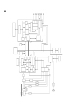
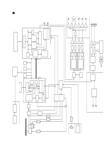
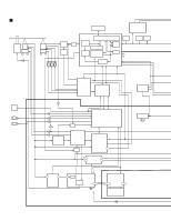
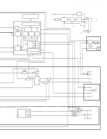
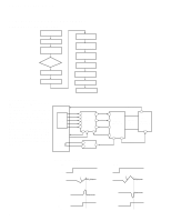
DV-505, DVL-909, DV-S9 1.2.3 Tracking / Slider Servo ATB: The tracking balance compensation is achieved by outputting the offset from the TBAL output at pin 46 of the digital servo IC, and by biasing the charge pump resistor for phase-difference error of RFIC. The difference is detected by processing TE at pin 34 of IC 201 with an internal digital equalizer. • TRACKING / SLIDER SERVO PICKUP OEIC TE RF B1 B2 B3 B4 4 TE 26 5 IC101 6 RFIC 7 TBAL 28 8 CP 34 IC201 DIGITAL ADDRESS SERVO IC 46 & BUS IC501 MECH. CONTROL TDO: In addition to the servo output, the lowband components, such as the kick-brake for jump, are added for TDO output. SLDO: The low-band components of TE are processed by the internal digital equalizer, and deadband is added for SLDO output. The offset voltage for pickup movement is also included in the SLDO output. TRKG COIL 50 47 26 24 TDO 27 IC151 DRIVER 16 19 SLDO 17 M SLDR 1.2.4 SPINDLE SERVO • SPDL SERVO ATC OEIC RF 3 IC101 RFIC 32 RF RFO 50 IC301 3 CLK (27M) A/D | 10 12 IC302 (1/2) 200 8 bit | 207 176 APC 178 AFC 180 ASC 177 179 IC701 LSI II 41 VCO 161 163 166 167 IC201 DIGITAL FG 57 SERVO 31 SPDL + 12 SPDL IC161 M DRV 25 48 SPDO SPDO (Compatible) FPWM VPWM PPWM IC271 (2/2) RPWM DUTY50 V165 IC271 (1/2) 13 SPDL (Base) For a CD, the RF signal output from pin 32 of the RF IC is converted to binary in IC201. By comparing the binary value with the reference CLK (clock), the SPDL ERR signal is output from pin 48. For a DVD, the SPDL ERR signal is generated from the PWM signal output from LSI-ΙΙ. Upon receiving this signal via pin 31, IC201 also outputs it from pin 48, switching from the CD SPDL ERR signal. 159 95 FG 7
-
 1
1 -
 2
2 -
 3
3 -
 4
4 -
 5
5 -
 6
6 -
 7
7 -
 8
8 -
 9
9 -
 10
10 -
 11
11 -
 12
12 -
13
-
14
-
15
-
16
-
17
-
18
-
19
-
20
-
21
-
22
-
23
-
24
-
25
-
26
-
27
-
28
-
29
-
30
-
31
-
32
-
33
-
34
-
35
-
36
-
37
-
38
-
39
-
40
-
41
-
42
-
43
-
44
-
45
-
46
-
47
 |
 |
