Poulan 1992-06 User Manual - Page 8
Cutters
 |
View all Poulan 1992-06 manuals
Add to My Manuals
Save this manual to your list of manuals |
Page 8 highlights
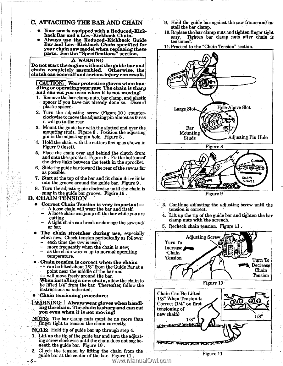
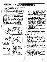
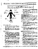
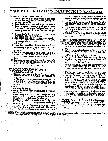
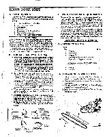
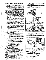
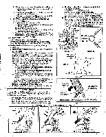
C. ATTACHING THE BAR AND CHAIN • Your saw is equipped with a Reduced-Kickback Bar and a Low-Kickback Chain. • Always use the Reduced-Kickback Guide Bar and Low-Kickback Chain specified for your chain saw model when replacing these parts. See the "Specifications section. A WARNING Do not start the engine without the guidebar and chain completely assembled. Otherwise, the clutch can come off and serious injury can result. CAUTION; Wearprotective gloves when handlingor operatingyour saw. The chain is sharp and can cut you even when it is not moving! 1. Remove thebar clamp nuts, bar clamp, and plastic spacer if you have not already done so. Discard plastic spacer. 2. Turn the adjusting screw (Figure 10) counterclockwise to move theadjustingpm almostas faras it will go to the rear. 3. Mount the guide bar with the slotted end over the mounting studs. Figure 8 . Position the adjusting pin in the adjusting pin hole. Figure 8 . 4. Hold the chain with the cutters facing as shown in Figure 9 (inset). 5. Place the chain over and behind the clutch drum and onto the sprocket. Figure 9 . Fit the bottom of the drive links between the teeth in the sprocket. 6. Slide the guide bar toward the rear of the sawas far as possible. 7. Start at the top of the bar and fit chain drive links into the groove around the guide bar Figure 9 . 8. Turn the adjusting pin clockwise until the chain is snug in the guide bar groove. Figure 10 . D. CHAIN TENSION • Correct Chain Tension is very important-- A loose chain will wear the bar and itself - A loose chain can jump off the bar while you are cutting - A tight chain can break or damage the sawand/ or bar. • The chain stretches during use, especially when new. Check tension periodically as follows: - each time the saw is used; - more frequently when the chain is new; - as the chain warms up to normal operating. temperature. • Chain tension is correct when the chain: - can be lifted about 1/8" from the Guide Bar at a point near the middle of the bar and - will move freely around the bar. When installinga newchain,allowthe chain to be lifted 1/4" from the bar. Thereafter, follow the instructions as indicated. • Chain tensioning procedure: WARNING: Alwayswear gloves when handl. ing the chain. The chain is sharp and can cut you even when it is not moving: NOTE; The bar clamp nuts must be no more than finger tight to tension the chain correctly. NOTE; Hold tip of guide bar up through step 4. L Lift up the tip of the guide bar and turn the adjust- ing screw clockwise until the chain does not sag beneath the guide bat Figure 10 . 2. Check the tension by lifting the chain from the guide bar at the center of the bar. Figure 11 . - 8- 9. Hold the guide bar against the saw frame and install the bar clamp. 10. Replace the bar clamp nuts and tighten finger tight only. Tighten bar clamp nuts after chain is tensioned. 11. Proceed to the "Chain Tension" section. Large Slo ore A ve Slot Bar Mounting Studs Adjusting Pin Hole Figure 8 Cutters CHAIN TRAVEL Figure 9 3. Cteonnsitoinnui.es adjusting colivi.t. the adjusting screw until the 4. Lift up the tip of the guide bar and tighten the bar clamp nuts with the scrench. 5. Recheck chain tension. Figure 11 . Adjusting Screw Turn To Increasers, Chain Tension Figure 10 Turn To Sok Decrease Chain Tension Chain Can Be Lifted 1/8" When Tension Is Correct (1/4" on first tensioning of new chain) 1/8" O_O 0 C 1/8" Figure 11
-
 1
1 -
2
-
 3
3 -
 4
4 -
 5
5 -
 6
6 -
 7
7 -
 8
8 -
 9
9 -
 10
10 -
 11
11 -
 12
12 -
 13
13 -
14
-
15
-
16
-
17
-
18
-
19
-
20
-
21
-
22
-
23
-
24
 |
 |