Poulan HDF825 User Manual - Page 12
Service And Adjustments, Maintenance
 |
View all Poulan HDF825 manuals
Add to My Manuals
Save this manual to your list of manuals |
Page 12 highlights
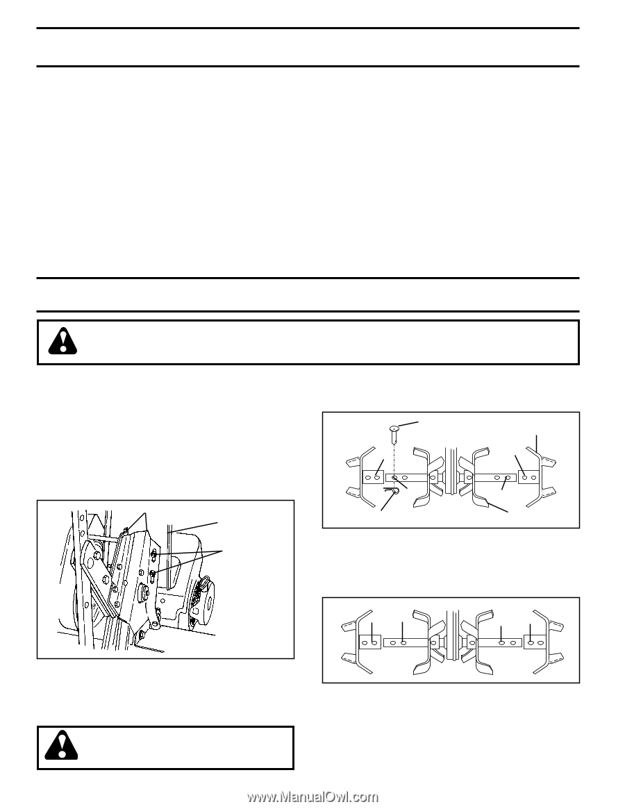
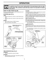
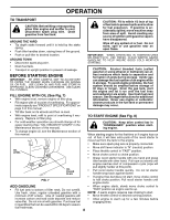
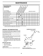
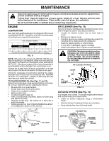
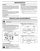
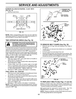
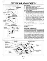
MAINTENANCE MUFFLER Do not operate tiller without muffler. Do not tamper with exhaust system. Damaged mufflers or spark arresters could create a fire hazard. Inspect periodically and replace if necessary. If your engine is equipped with a spark arrester screen assembly, remove every 50 hours for cleaning and inspection. Replace if damaged. SPARK PLUG Replace spark plugs at the beginning of each tilling season or after every 50 hours of use, whichever comes first. Spark plug type and gap setting are shown in "PRODUCT SPECIFICATIONS" on page 3 of this manual. TRANSMISSION Your transmission is sealed and will not require lubrication unless serviced. CLEANING Do not clean your tiller when the engine and transmission are hot. We do not recommend using pressurized water (garden hose, etc.) to clean your unit unless the gasket area around the transmission and the engine muffler, air filter and carburetor are covered to keep water out. Water in engine will shorten the useful life of your tiller. • Clean engine, wheels, finish, etc. of all foreign matter. • Keep finished surfaces and wheels free of all gasoline, oil, etc. • Protect painted surfaces with automotive type wax. SERVICE AND ADJUSTMENTS CAUTION: Disconnect spark plug wire from spark plug and place wire where it cannot come into contact with plug. TILLER TO ADJUST HANDLE HEIGHT (See Fig. 15) Factory assembly has provided lowest handle height. Select handle height best suited for your tilling conditions. Handle height will be different when tiller digs into soil. • If a higher handle height is desired, loosen the four nuts securing handle panel to engine brackets. • Slide handle panel to desired location. • Tighten the four nuts securely. ENGINE BRACKETS HANDLE PANEL NUTS (ALSO 2 ON LEFT SIDE OF TILLER) NORMAL TILLING - 26" PATH (See Fig. 16) • Assemble holes "A" in tine hubs to holes "B" in tine shaft. CLEVIS PIN OUTER TINE A A B tine_4 HAIRPIN CLIP FIG. 16 B INNER TINE MID-WIDTH TILLING - 24" PATH (See Fig. 17) • Assemble holes "A" in tine hubs to holes "C" in tine shaft. A C C A FIG. 15 tine_5 TINE ARRANGEMENT Your outer tines can be assembled in several different ways to suit your tilling or cultivating needs. CAUTION: Tines are sharp. Wear gloves or other protection when handling tines. 12 FIG. 17
-
 1
1 -
2
-
3
-
4
-
5
-
6
-
 7
7 -
 8
8 -
 9
9 -
 10
10 -
 11
11 -
 12
12 -
 13
13 -
 14
14 -
 15
15 -
 16
16 -
 17
17 -
18
-
19
-
20
-
21
-
22
-
23
-
24
-
25
-
26
-
27
-
28
-
29
-
30
-
31
-
32
-
33
-
34
-
35
-
36
 |
 |