Poulan HDF825 User Manual - Page 7
How To Use Your Tiller
 |
View all Poulan HDF825 manuals
Add to My Manuals
Save this manual to your list of manuals |
Page 7 highlights
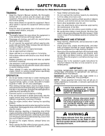
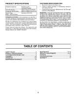
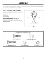
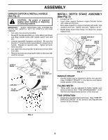
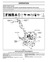
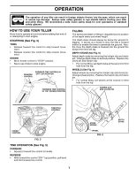
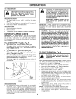
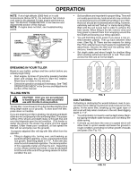
OPERATION The operation of any tiller can result in foreign objects thrown into the eyes, which can result in severe eye damage. Always wear safety glasses or eye shields before starting your tiller and while tilling. We recommend a wide vision safety mask for over spectacles or standard safety glasses. HOW TO USE YOUR TILLER Know how to operate all controls before adding fuel and oil or attempting to start engine. STOPPING (See Fig. 5) TINES • Release forward tine control to stop forward move- ment. • Release reverse tine control to stop reverse move- ment. ENGINE • Move throttle control to "STOP" position. • Never use choke to stop engine. REVERSE CONTROL FORWARD TINE CONTROL IN "OFF" (UP) POSITION FORWARD TINE CONTROL IN "ON" (DOWN) POSITION TILLING The speed and depth of tilling is regulated by the position of the depth stake and wheel height. The depth stake should always be below the wheels for digging. It serves as a brake to slow the tiller's forward motion to enable the tines to penetrate the ground. Also, the more the depth stake is lowered into the ground the deeper the tines will dig. DEPTH STAKE (See Fig. 6) Adjust depth stake by removing the hairpin clip and clevis pin. Change depth stake to desired position. Replace the clevis pin and hairpin clip. • For normal tilling, set depth stake at the second or third hole from the top. WHEELS (See Fig. 6) Adjust wheels by removing the hairpin clip and clevis pin. Change wheel position. Replace the hairpin clip and clevis pin. • For normal tilling, set wheels at the second or third hole from the top. depth_stake_4 HAIRPIN CLIP AND CLEVIS PIN handles_94 THROTTLE CONTROL CHOKE CONTROL engine_art_71 FIG. 5 TINE OPERATION (See Fig. 5) FORWARD • Squeeze forward tine control to handle. REVERSE • With forward tine control "OFF" (up) position, pull back and hold reverse tine control. 7 STAKE SPRING WHEEL FIG. 6 DEPTH STAKE
-
 1
1 -
 2
2 -
 3
3 -
 4
4 -
 5
5 -
 6
6 -
 7
7 -
 8
8 -
 9
9 -
 10
10 -
 11
11 -
 12
12 -
13
-
14
-
15
-
16
-
17
-
18
-
19
-
20
-
21
-
22
-
23
-
24
-
25
-
26
-
27
-
28
-
29
-
30
-
31
-
32
-
33
-
34
-
35
-
36
 |
 |