Poulan PP1644JA User Manual - Page 8
Install, Mower, Drive, Figs.
 |
View all Poulan PP1644JA manuals
Add to My Manuals
Save this manual to your list of manuals |
Page 8 highlights
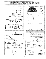
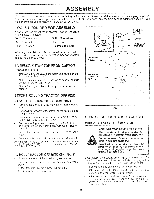
ASSEMBLY INSTALL MOWER AND DRIVE BELT (See Figs. 5 and 8) Be sure tractor is on level surface. Engage parking brake. • Cut and remove tie down wire holding anti-sway bar. Swing anti-sway bar to left side of mower deck. • Relieve idler tension from belt. Push idler forward and place a block (standard wood 2 x 4 or equivalent) behind idler pulley. • Slide mower undertractor with discharge guard to right side of tractor. • Install one front link in top hole of the L.H. front mower bracket and L.H. front suspension bracket. Retain with two single loop retainer springs as shown. • Slide right side of mower deck forward, toward R.H. front tire. • Checkbelt forproper routinginallmowerpulley grooves. Install belt into electric clutch pulley groove. • Install second front link in the top hole of the R.H. front mower bracket and R.H. front suspension bracket. Retain with two single loop retainer springs as shown. • Carefully remove block from behind idler pulley. • Turn height adjustment knob counterclockwise until it stops. • Lower mower linkage with attachment lift lever. • Place the suspension arms on outward pointing deck pins. If necessary, raise front of mower to align deck pins with the holes in suspension arms. Retain with double loop retainer springs. • Connect anti-sway bar to chassis bracket under left footrest and retain with double loop retainer spring. • Turn height adjustment knob clockwise to remove slack from mower suspension. • Raise deck to highest position. CHASSIS BRACKET SUSPENSION ARMS DOUBLE LOOP RETAINER SPRING (OUTWARD POINTING DECK PINS) sl FRONT LINKS 1 1. FRONT SUSPENSION BRACKET e/ 1. ELECTRIC CLUTCH PULLEY a." DOUBLE LOOP RETAINER SPRING ;f9 ANTI-SWAY BAR IDLER PULLEY SINGLE LOOP RETAINER SPRINGS FRONT MOWER BRACKET DISCHARGE GUARD FIG. 5 8
-
 1
1 -
2
-
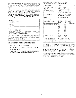 3
3 -
 4
4 -
 5
5 -
 6
6 -
 7
7 -
 8
8 -
 9
9 -
 10
10 -
 11
11 -
 12
12 -
 13
13 -
14
-
15
-
16
-
17
-
18
-
19
-
20
-
21
-
22
-
23
-
24
-
25
-
26
-
27
-
28
-
29
-
30
-
31
-
32
-
33
-
34
-
35
-
36
-
37
-
38
-
39
-
40
-
41
-
42
-
43
-
44
-
45
-
46
-
47
-
48
 |
 |
