Poulan PPB4000C User Manual - Page 10
Use Of Brushcutter Attach
 |
View all Poulan PPB4000C manuals
Add to My Manuals
Save this manual to your list of manuals |
Page 10 highlights
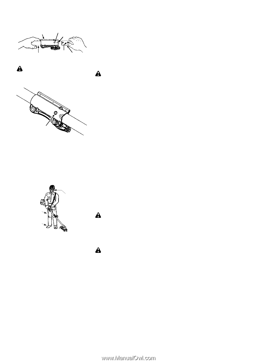
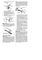
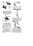
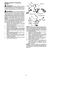
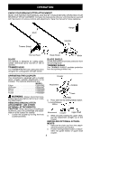
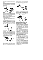
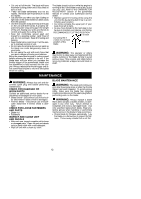
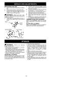
3. Push the attachment into the coupler until the locking/release button snaps into the primary hole. 4. Before using the unit, tighten the knob se- curely by turning clockwise. Coupler Primary Hole Guide Recess Upper Shaft Locking/ Release Attachment Button WARNING: Make sure the locking/re- lease button is locked in the primary hole and the knob is securely tightened before operating the unit. Using the wrong hole could lead to serious injury or damage to the unit. Locking/Release Button in Primary Hole INSTALLING ATTACHMENT HANGER An attachment hanger is provided for storage when attachment is not in use. To install hanger on attachment: 1. Remove the shaft cap from the attach- ment (if present) and discard. 2. Press and hold the locking/release but- ton. 3. Push hanger onto the attachment until the locking/release button snaps into the hole. OPERATING POSITION ALWAYS WEAR: Eye Protection Heavy, Long Pants Boots Cut from your left to your right. NOTE: This brushcutter attachment is not designed for use with electric powerheads. When operating unit with brushcutter attachment, clip shoulder strap onto upper shoulder strap clamp, stand as shown and check for the following: S Wear eye protection and heavy clothing. S Keep arms extended with right hand holding the trigger handle of powerhead. S Keep left arm extended with left hand hold- ing the handlebar. S Keep unit below waist level. S Shoulder strap pad should be centered on your left shoulder and danger sign centered on your back. S Maintain full weight of tool on left shoulder. S Without bending over, keep the blade near and parallel to the ground and not crowded into material being cut. OPERATING INSTRUCTIONS FOR USE OF BRUSHCUTTER ATTACHMENT WITH TRIMMER HEAD WARNING: Always wear eye protec- tion. Never lean over the trimmer head. Rocks or debris can ricochet or be thrown into eyes and face and cause blindness or other serious injury. Before trimming, bring engine to a speed sufficient to cut material to be trimmed. Do not run the engine at a higher speed than necessary. The cutting line will cut efficiently when the engine is run at less than full throttle. At lower speeds, there is less engine noise and vibration. Always release the throttle trigger and allow the engine to return to idle speed when not cutting. TRIMMER LINE ADVANCE The trimmer line will advance approximately 2 inches (5 cm) each time the bottom of the trimmer head is tapped on the ground with the engine running at full throttle. The most efficient line length is the maximum length allowed by the line limiter. Always keep the shield in place when the tool is being operated. To advance line: S Operate the engine at full throttle. S Hold the trimmer head parallel to and above the grassy area. S Tap the bottom of the trimmer head lightly on the ground one time. Approximately 2 inches (5 cm) of line will be advanced with each tap. Always tap the trimmer head on a grassy area. Tapping on surfaces such as concrete or asphalt can cause excessive wear to the trimmer head. If the line is worn down to 2 inches (5 cm) or less, more than one tap will be required to obtain the most efficient line length. WARNING: Use only 0.080″ (2 mm) diameter line. Other sizes of line will not advance properly and can cause serious injury. Do not use other materials such as wire, string, rope, etc. Wire can break off during cutting and become a dangerous missile that can cause serious injury. CUTTING METHODS WARNING: Use minimum speed and do not crowd the line when cutting around hard objects (rock, gravel, fence posts, etc.), which can damage the trimmer head, become entan- 10
-
 1
1 -
2
-
3
-
4
-
 5
5 -
 6
6 -
 7
7 -
 8
8 -
 9
9 -
 10
10 -
 11
11 -
 12
12 -
 13
13 -
 14
14
 |
 |