Poulan PPB4000C User Manual - Page 5
Warning, Danger
 |
View all Poulan PPB4000C manuals
Add to My Manuals
Save this manual to your list of manuals |
Page 5 highlights
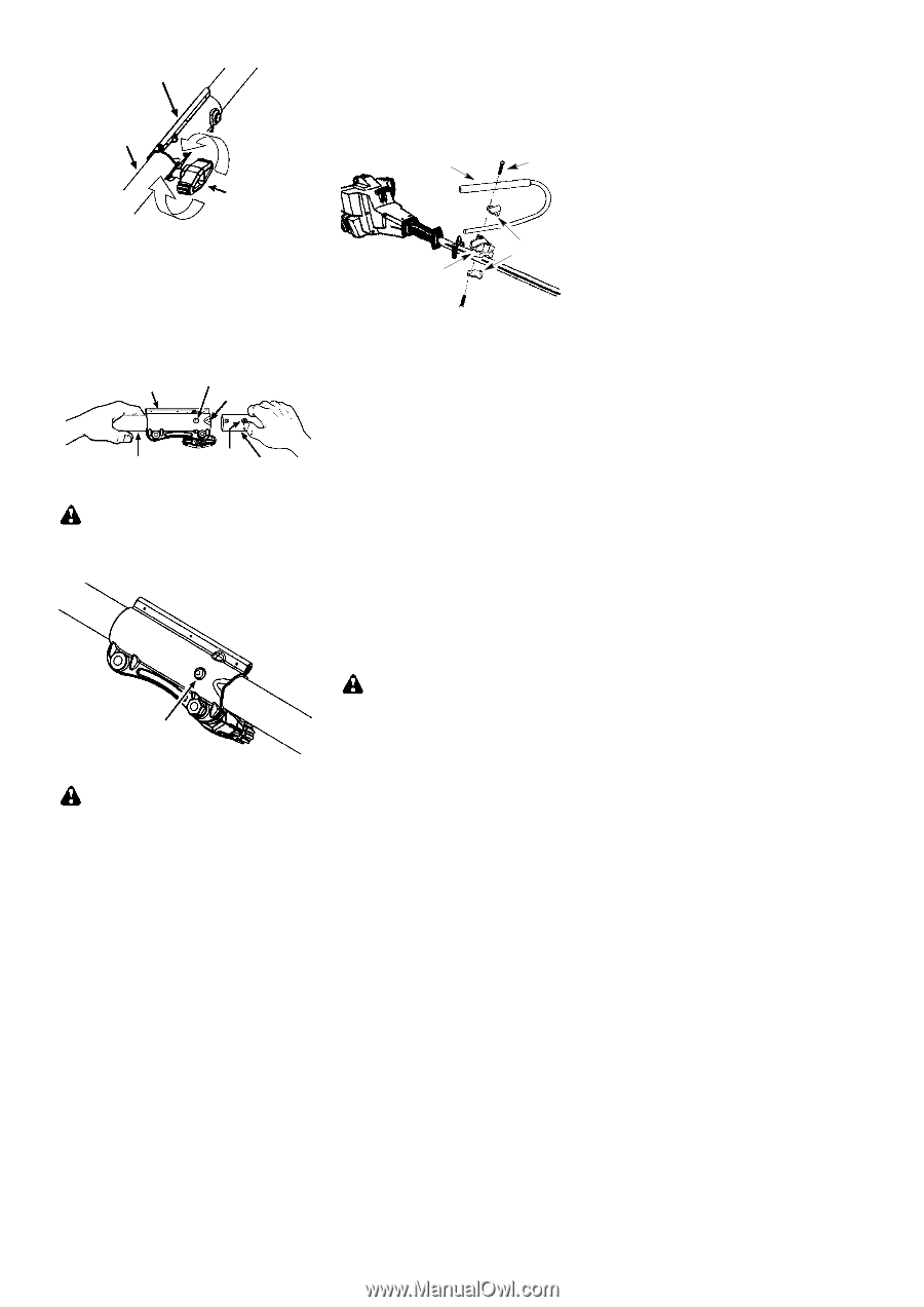
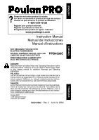
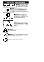
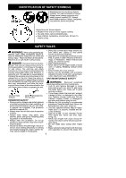
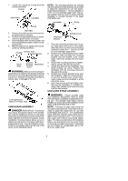
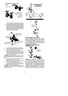
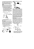
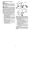
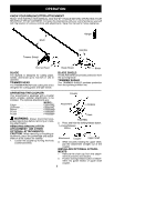
1. Loosen the coupler by turning the knob counterclockwise. Coupler Attachment LOOSEN Knob TIGHTEN 2. Remove the shaft cap from the brushcutter attachment (if present). 3. Position locking/release button of attachment into guide recess of coupler. 4. Push the attachment into the coupler until the locking/release button snaps into the primary hole. 5. Before using the unit, tighten the knob securely by turning clockwise. Coupler Primary Hole Guide Recess Upper Shaft Locking/ Release Attachment Button WARNING: Make sure the locking/re- lease button is locked in the primary hole and the knob is securely tightened before operating the unit. Using the wrong hole could lead to serious injury or damage to the unit. Locking/Release Button in Primary Hole HANDLEBAR ASSEMBLY DANGER: RISK OF CUT. To avoid se- rious injury, the barrier portion of the handlebar must be installed as shown on the upper shaft of the powerhead to provide a barrier between operator and the spinning blade. Attach handlebar mounting bracket above arrow on safety warning decal on the upper shaft (powerhead end of unit). Ensure handlebar is positioned on mounting bracket at the end of the arrow on the handlebar decal. NOTE: Two mounting brackets are included with this attachment. Both brackets are provided to adapt this attachment for use with powerheads that have either a 1″ (2.5 cm) diameter or a 7/8″ (2.2 cm) diameter upper shaft. The correct bracket must be used to ensure that the handlebar is mounted securely to the upper shaft before use. Handlebar Screw Mounting Bracket Bracket Cover 1. Place the mounting bracket over the upper shaft above the arrow on the safety label. Be sure to use the correct mounting bracket for either the 1″ (2.5 cm) or 7/8″ (2.2 cm) diameter upper shaft. 2. Position one of the bracket covers under the upper shaft and align the mounting bracket and the bracket cover screw holes. Insert two screws into the screw holes. 3. Secure the mounting bracket by tightening the screws with the hex wrench. 4. Locate the decal on the handlebar. This decal includes an arrow. Position the handlebar with the mounting bracket at the end of the arrow. 5. Position the second bracket cover over the handlebar. Align the mounting bracket and the bracket cover screw holes. Again make sure the handlebar is at the end of the arrow. 6. Insert two screws and hand tighten only. Be sure the handlebar is installed correctly; then, tighten each screw securely with the hex wrench. SHOULDER STRAP ASSEMBLY WARNING: Proper shoulder strap and handlebar adjustments must be made with the engine completely stopped before using unit. The shoulder strap clamp must be installed as shown above the handlebar on the upper shaft (powerhead end of unit). NOTE: The lower shoulder strap clamp has two spacer tabs attached. These tabs are provided to adapt this attachment for use with powerheads that have a 1″ (2.5 cm)diameter upper shaft (the shoulder strap clamp will not tighten down securely on the 1″ (2.5 cm) diameter upper shaft without using these spacer tabs). The tabs must be broken off completely before use and placed over the screw holes on the lower shoulder strap clamp. These tabs are not needed for powerheads with a 7/8″ (2.2 cm) upper shaft. 5
-
 1
1 -
 2
2 -
 3
3 -
 4
4 -
 5
5 -
 6
6 -
 7
7 -
 8
8 -
 9
9 -
 10
10 -
 11
11 -
12
-
13
-
14
 |
 |