Poulan PPB4000C User Manual - Page 6
Configuring Your Unit, Assembly Information, Trimmer Head
 |
View all Poulan PPB4000C manuals
Add to My Manuals
Save this manual to your list of manuals |
Page 6 highlights
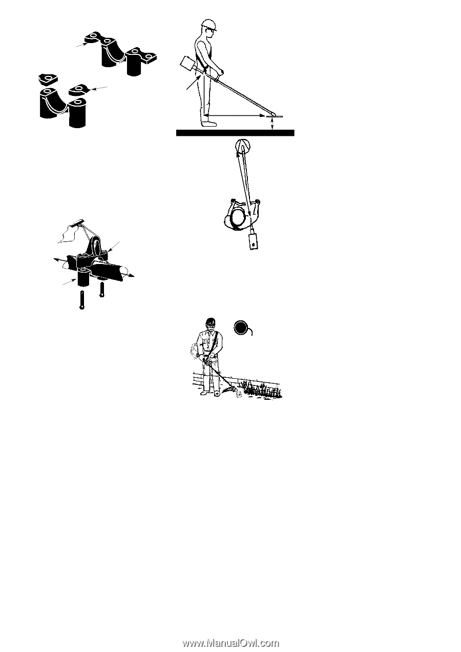
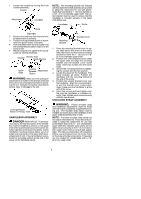
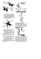
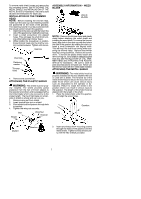
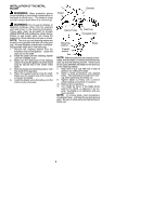
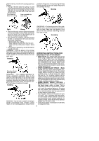
LOWER SHOULDER STRAP CLAMP Spacer Tabs SHOULDER STRAP ADJUSTMENT FOR BALANCE Spacer Tabs positioned for use on 1″ (2.5 cm) diameter upper shaft 6 inches (15 cm) below waist 30 inches (76 cm) minimum 4 -- 12 inches (10 -- 30 cm) above ground 1. Place the upper shoulder strap clamp over the upper shaft above the handlebar. 2. Position the lower shoulder strap clamp under the upper shaft and align the upper and lower clamp screw holes (use spacer tabs between upper and lower clamps if necessary to secure clamp, i.e. for 1″ (2.5 cm) diameter upper shaft). 30 inches (76 cm) minimum POWERHEAD END Upper Shoulder Strap Clamp Lower Shoulder Strap Clamp ATTACHMENT END Screws 3. Insert two screws into the screw holes. 4. Secure shoulder strap clamp by tighten- ing screws with the hex wrench. 5. Insert your right arm and head through the shoulder strap and allow it to rest on your left shoulder. Make sure the danger sign is on your back and the hook is to the right side of your waist. NOTE: A one-half twist is built in the shoulder strap to allow the strap to rest flat on the shoulder. 6. Adjust the strap, allowing the hook to be about 6 inches below the waist. 7. Fasten the strap hook to the clamp and lift the tool to the operating position. 8. Try on shoulder strap and adjust for fit and balance before starting the engine or beginning a cutting operation. NOTE: It may be necessary to relocate the shoulder strap clamp on the shaft for proper balancing of unit. CONFIGURING YOUR UNIT You can configure your unit using a trimmer head for grass and light weeds, or a weed blade for cutting grass, weeds, and brush up to 1/2 inch (1 cm) in diameter. To assemble your unit, go to the section for the desired configuration and follow the instructions. ASSEMBLY INFORMATION -TRIMMER HEAD TRIMMER HEAD NOTE: Remove the blade and metal shield before attaching the plastic shield and trimmer head. To remove blade, align hole in the dust cup with the hole in the side of the gearbox by rotating the blade. Insert a small screwdriver into aligned holes. This will keep the shaft from turning while loosening the blade nut. Remove blade nut by turning clockwise. Remove the screwdriver. Remove both washers and blade. 6
-
 1
1 -
 2
2 -
 3
3 -
 4
4 -
 5
5 -
 6
6 -
 7
7 -
 8
8 -
 9
9 -
 10
10 -
 11
11 -
 12
12 -
13
-
14
 |
 |