Poulan XC1182B User Manual - Page 7
Assembly
 |
View all Poulan XC1182B manuals
Add to My Manuals
Save this manual to your list of manuals |
Page 7 highlights
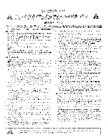
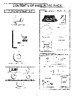
ASSEMBLY TOOLS REQUIRED FOR ASSEMBLY A socket wrench set will make assembly easier. Standard wrench sizes are listed. (2) 7/16" wrenches (1) Tire Pressure Gauge (1) Adjustable Wrench (1) Utility Knife When right or left hand is mentioned in this manual, it means when you are in the operating position (seated behind the steering wheel). TO REMOVE UNIT FROM CARTON UNPACK CARTON • Remove all loose parts from carton (See page 6). • Cut, from top to bottom, all four corners of carton and lay panels flat. • Remove mower deck from skid. ATTACH STEERING WHEEL (See FIG. 1) • Remove hex nut and large flat washer from steering shaft. • Position front wheels of the tractor so they are pointing straight forward. • Position steering wheel so cross bars are horizontal (left to right) and slide onto adapter. • Secure steering wheel to steering shaft with hex nut and large flat washer previously removed. Tighten securely. • Snap insert into center of steering wheel. • Remove protective plastic from tractor hood. BEFORE ROLLING UNIT OFF SKID (See FIG. 2) IMPORTANT: CHECK FOR AND REMOVE ANY STAPLES IN SKID THAT MAY PUNCTURE TIRES WHERE UNIT IS TO ROLL OFF SKID. • Raise attachment lift lever to its highest position. • Release parking brake by depressing clutch/brake pedal. • Place gearshift lever in "NEUTRAL" position. • Roll unit backwards off skid. STEERING WHEEL INSERT HEX NUT FLAT WASHER MHO f r STEERING WHEEL STEERING WHEEL ADAPTER STEERING SHAFT FIG. 1 CLUTCH/BRAKE PEDAL LIFT LEVER 0 PARKING BRAKE GEAR SHIFT LEVER FIG. 2
-
 1
1 -
 2
2 -
 3
3 -
 4
4 -
 5
5 -
 6
6 -
 7
7 -
 8
8 -
 9
9 -
 10
10 -
 11
11 -
 12
12 -
13
-
14
-
15
-
16
-
17
-
18
-
19
-
20
-
21
-
22
-
23
-
24
-
25
-
26
-
27
-
28
-
29
-
30
-
31
-
32
 |
 |
