ProForm 3.6 Uk Manual - Page 11
If The Connectors Are Not Con
 |
View all ProForm 3.6 manuals
Add to My Manuals
Save this manual to your list of manuals |
Page 11 highlights
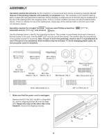
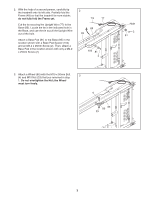
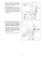
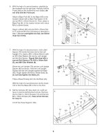
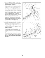
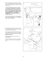
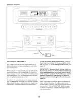
11. Have a second person hold the console assembly near the Right Upright (78). Remove the long tie from the Upright Wire (77) and the tie from the console wire. Connect the Upright Wire (77) to the console wire. See the inset drawing. The connectors should slide together easily and snap into place. If they do not, turn one connector and try again. IF THE CONNECTORS ARE NOT CONNECTED PROPERLY, THE CONSOLE MAY BE DAMAGED WHEN THE POWER IS TURNED ON. Then, insert the connectors into the Right Upright (78). Set the console assembly on the Right Upright (78) and the Left Upright (not shown). Make sure that no wires are pinched. 11 90 77 Console Assembly Console Wire Long Tie Console Wire 77 78 12. Finger tighten three M8 x 25mm Bolts (6) with 12 three M8 Star Washers (10) into the Left Upright (73) and the Left Handrail (89). Next, finger tighten three M8 x 25mm Bolts (6) with three M8 Star Washers (10) into the Right Upright (78) and the Right Handrail (90). Then, tighten all six Bolts. See steps 5 and 7. Tighten the four M10 x 96mm Bolts (5). 110 111 88 Press the Left Accessory Tray (110) and Right 89 Accessory Tray (111) into the Console Base (88). 10 6 10 6 6 10 73 90 78 10 6 11
-
 1
1 -
2
-
3
-
4
-
5
-
 6
6 -
 7
7 -
 8
8 -
 9
9 -
 10
10 -
 11
11 -
 12
12 -
 13
13 -
 14
14 -
 15
15 -
 16
16 -
17
-
18
-
19
-
20
-
21
-
22
-
23
-
24
-
25
-
26
-
27
-
28
-
29
-
30
-
31
-
32
 |
 |
