ProForm 3.6 Uk Manual - Page 9
second Bolt Spacer 79, M10 x 96mm Bolt
 |
View all ProForm 3.6 manuals
Add to My Manuals
Save this manual to your list of manuals |
Page 9 highlights
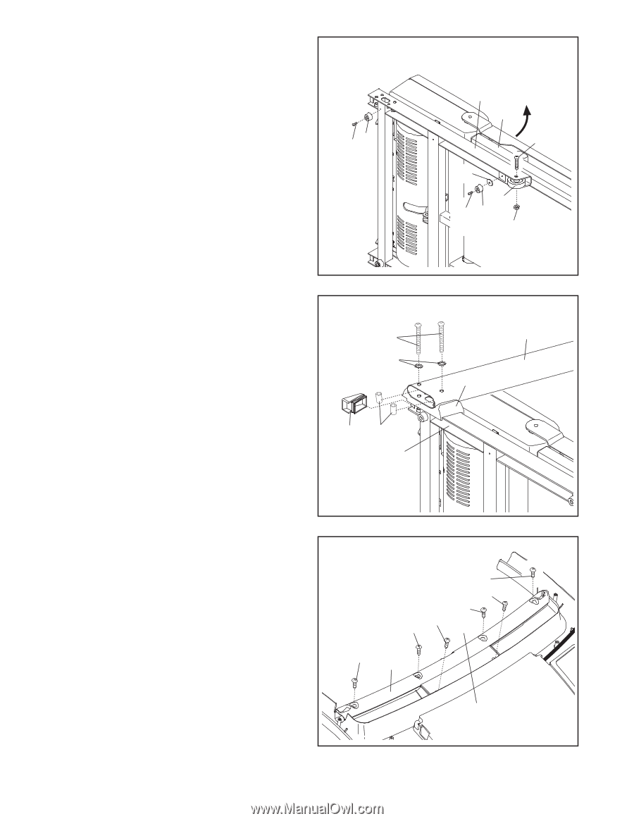
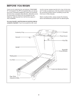
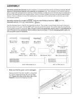
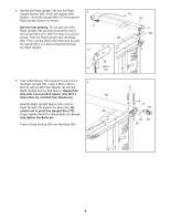
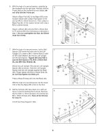
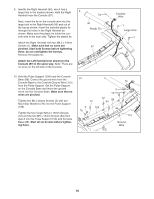
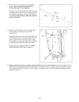
6. With the help of a second person, carefully tip the treadmill onto its right side. Partially fold the Frame (48) so the treadmill is more stable; do not fully fold the Frame yet. Attach a Base Pad (81) to the Base (85) in the location shown with a Base Pad Spacer (104) and an M4.2 x 25mm Screw (2). Then, attach a Base Pad (81) in the location shown with only a M4.2 x 25mm Screw. Attach a Wheel (86) with the M10 x 50mm Bolt (127) and the M10 Nut (33) that you removed in step 1. Do not overtighten the Nut; the Wheel must turn freely. 6 81 2 85 48 127 104 86 2 81 33 7. With the help of a second person, hold a Bolt Spacer (79) inside the lower end of the Left Upright (73). Insert a M10 x 96mm Bolt (5) with an M10 Star Washer (8) into the Left Upright and the Bolt Spacer. Repeat this step with a second Bolt Spacer (79), M10 x 96mm Bolt (5), and M10 Star Washer (8). Orient the Left Upright (73) and the Left Upright Spacer (83) as shown. Hold the Left Upright Spacer and the Left Upright against the Base (85). Finger tighten the M10 x 96mm Bolts (5); do not fully tighten the Bolts yet. Press a Base Endcap (82) into the Base (85). With the help of a second person, tip the treadmill so that the Base (85) is flat on the floor. 8. Set the Console (87) face down on a soft surface to avoid scratching the Console. Remove the four M4.2 x 16mm Screws (12) and the two M5 x 15mm Screws (64). Save all six Screws for step 10. Lift off the Pulse Support (109). 7 5 8 82 79 85 73 83 8 64 12 12 64 12 87 12 109 9
-
 1
1 -
2
-
3
-
 4
4 -
 5
5 -
 6
6 -
 7
7 -
 8
8 -
 9
9 -
 10
10 -
 11
11 -
 12
12 -
 13
13 -
 14
14 -
15
-
16
-
17
-
18
-
19
-
20
-
21
-
22
-
23
-
24
-
25
-
26
-
27
-
28
-
29
-
30
-
31
-
32
 |
 |