ProForm 3.6 Uk Manual - Page 7
Do not overtighten the Nut; the Wheel, must turn freely., do not fully fold the Frame yet.
 |
View all ProForm 3.6 manuals
Add to My Manuals
Save this manual to your list of manuals |
Page 7 highlights
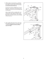
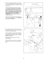
2. With the help of a second person, carefully tip the treadmill onto its left side. Partially fold the Frame (48) so that the treadmill is more stable; do not fully fold the Frame yet. Cut the tie securing the Upright Wire (77) to the Base (85). Locate the tie in the indicated hole in the Base, and use the tie to pull the Upright Wire out of the hole. Attach a Base Pad (81) to the Base (85) in the location shown with a Base Pad Spacer (104) and an M4.2 x 25mm Screw (2). Then, attach a Base Pad in the location shown with only a M4.2 x 25mm Screw (2). 2 Tie 77 85 48 104 81 2 Hole 2 81 3. Attach a Wheel (86) with the M10 x 50mm Bolt 3 (4) and M10 Nut (33) that you removed in step 1. Do not overtighten the Nut; the Wheel must turn freely. 4 85 86 33 7
-
 1
1 -
 2
2 -
 3
3 -
 4
4 -
 5
5 -
 6
6 -
 7
7 -
 8
8 -
 9
9 -
 10
10 -
 11
11 -
 12
12 -
13
-
14
-
15
-
16
-
17
-
18
-
19
-
20
-
21
-
22
-
23
-
24
-
25
-
26
-
27
-
28
-
29
-
30
-
31
-
32
 |
 |
