ProForm 305 Cst Instruction Manual - Page 8
See the inset drawing.
 |
View all ProForm 305 Cst manuals
Add to My Manuals
Save this manual to your list of manuals |
Page 8 highlights
3. Identify the Right Upright (76). Have a second person hold the Right Upright near the Base (74). 3 63 D 63 See the inset drawing. Tie the wire tie (D) in the Right Upright (76) securely around the end of the Upright Wire (63). Then, insert the Upright Wire into the lower end of the Right Upright as you pull the other end of the wire tie through the top of the Right Upright. 76 D 76 74 4. Lay the Right Upright (76) near the Base (74) as shown. 4 If there is a screw (E) preattached to the Right Upright (76), remove and discard it. Attach the ground wire (F) to the Base with a #8 x 1/2" Ground Screw (1). Then, press the Upright Grommet (73) into the square hole (G) in the Right Upright (76). 74 1 F E 76 73 G 8
-
 1
1 -
2
-
 3
3 -
 4
4 -
 5
5 -
 6
6 -
 7
7 -
 8
8 -
 9
9 -
 10
10 -
 11
11 -
 12
12 -
 13
13 -
14
-
15
-
16
-
17
-
18
-
19
-
20
-
21
-
22
-
23
-
24
-
25
-
26
-
27
-
28
-
29
-
30
-
31
-
32
 |
 |

8
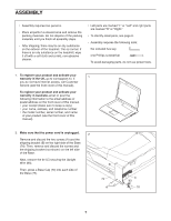
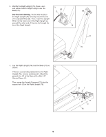
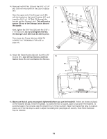
4.
Lay the Right Upright (76) near the Base (74) as
shown.
If there is a screw (E) preattached to the Right
Upright (76), remove and discard it. Attach the
ground wire (F) to the Base with a #8 x 1/2"
Ground Screw (1).
Then, press the Upright Grommet (73) into the
square hole (G) in the Right Upright (76).
74
74
76
76
63
1
76
D
3
4
63
D
G
E
F
3.
Identify the Right Upright (76). Have a sec-
ond person hold the Right Upright near the
Base (74).
See the inset drawing.
Tie the wire tie (D) in
the Right Upright (76) securely around the end
of the Upright Wire (63). Then, insert the Upright
Wire into the lower end of the Right Upright as
you pull the other end of the wire tie through the
top of the Right Upright.
73