ProForm 650 Elliptical Uk Manual - Page 9
Button Bolts 67. See step 10. Tighten the M8 x
 |
View all ProForm 650 Elliptical manuals
Add to My Manuals
Save this manual to your list of manuals |
Page 9 highlights
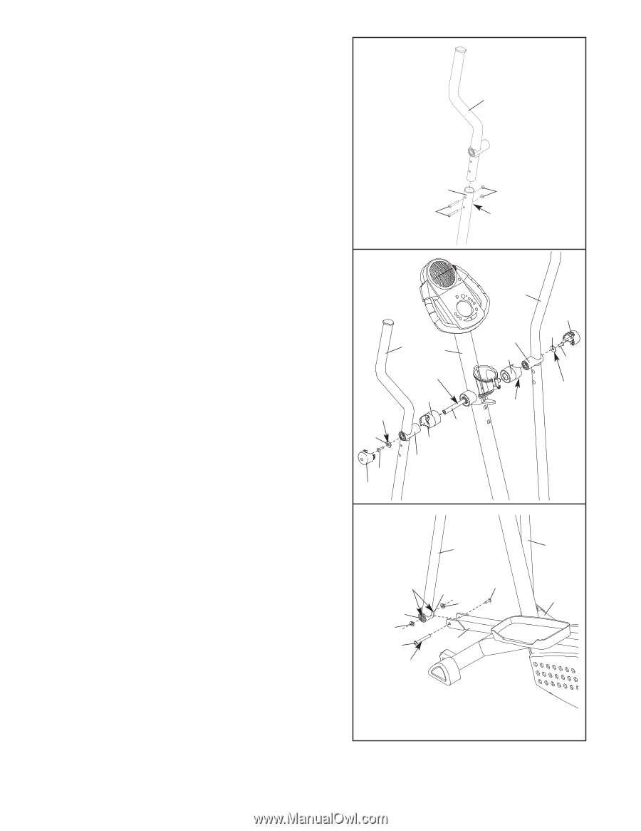
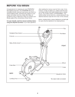
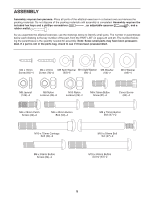
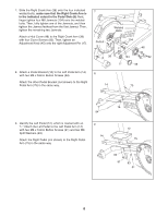
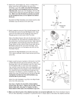
10. Identify the Left Handlebar (9), which is marked with a sticker. Insert the Left Handlebar into one of the 10 Handlebar Legs (79); make sure that the Handlebar Leg is turned so the hexagonal holes are on the indicated side. Attach the Left Handlebar with two M8 x 45mm Button Bolts (50) and two M8 Nylon Locknuts (46). Make sure that the Nylon Locknuts are inside of the hexagonal holes. Do not tighten the Button Bolts yet. Assemble the Right Handlebar (not shown) and the other Handlebar Leg (not shown) in the same way. 9 79 50 46 Hexagonal Holes 11. Apply a generous amount of the included grease to the Pivot Axle (81) and to the two M8 Washers (53). Next, insert the Pivot Axle into the Upright (2) and centre it. Reapply grease to both ends of the Pivot Axle. Slide a Handlebar Spacer (25) onto the short tube on the Left Handlebar (9), and rotate the Handlebar Spacer so the small arrow is pointing toward the floor. Next, slide the Left Handlebar onto the left end of the Pivot Axle (81). Finger tighten an M8 x 25mm Patch Screw (22) with an M8 Washer (53) into the end of the Pivot Axle. Then, press the small tabs on a Handlebar Cap (23) into the Handlebar Spacer. Assemble the Right Handlebar (10) in the same way. Then, tighten both M8 x 25mm Patch Screws (22) at the same time. 12. Apply a small amount of grease to the barrel of an M10 x 59mm Bolt Set (27) and to the surfaces of the Leg Bushings (28) in the left Handlebar Leg (79). Next, hold an M10 Washer (98) on each side of the Handlebar Leg, and then insert the lower end of the Handlebar Leg and the Washers into the bracket on the Left Pedal Arm (14). Insert the barrel of the Bolt Set through the Left Pedal Arm, the Washers, and the Handlebar Leg. Then, tighten the screw of the Bolt Set into the barrel. Do not overtighten the Bolt Set; the left Handlebar Leg must be able to pivot freely. Attach the right Handlebar Leg (79) to the Right Pedal Arm (75) in the same way. See step 3. Tighten the two M10 x 83mm Button Screws (63). See step 4. Tighten the two M8 x 70mm Button Bolts (67). See step 10. Tighten the M8 x 45mm Button Bolts (50) in the Handlebar Legs (79). 11 9 2 Grease Grease 53 22 23 25 81 Arrow Tube 12 79 Grease 28 98 27 Grease 28 98 14 10 Tube 25 Arrow 27 23 53 22 Grease 79 75 13. Make sure that all parts of the elliptical exerciser are properly tightened. Note: Some hardware may be left over after assembly is completed. To protect the floor or carpet, place a mat under the elliptical exerciser. 9
-
 1
1 -
2
-
3
-
 4
4 -
 5
5 -
 6
6 -
 7
7 -
 8
8 -
 9
9 -
 10
10 -
 11
11 -
 12
12 -
 13
13 -
 14
14 -
15
-
16
-
17
-
18
-
19
-
20
-
21
-
22
-
23
-
24
-
25
-
26
-
27
-
28
 |
 |