ProForm Performance 950 Instruction Manual - Page 13
Lower the Frame 55 see HOW TO LOWER
 |
View all ProForm Performance 950 manuals
Add to My Manuals
Save this manual to your list of manuals |
Page 13 highlights
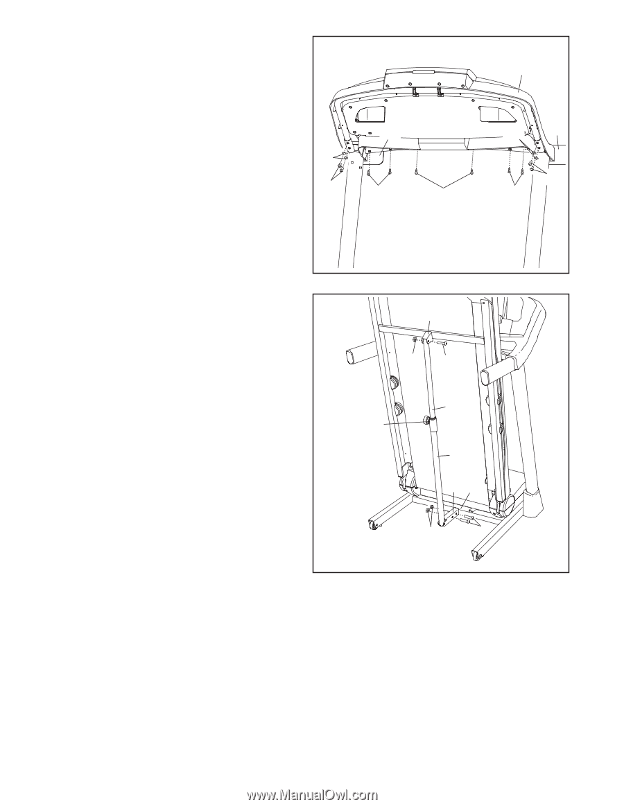
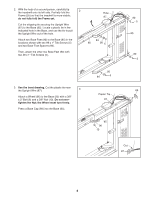
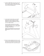
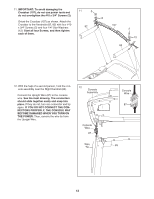
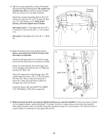
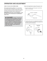
13. Set the console assembly on the Left Handrail (82) and the Right Handrail (83). Be careful not 13 to pinch any wires. Insert the excess Upright Wire (not shown) into the Right Handrail. Attach the console assembly with six #8 x 3/4" Screws (1) and four 1/4" x 1/2" Screws (9) with four 1/4" Star Washers (12). Start all ten Screws, and then tighten each of them. 83 See steps 5 and 7. Fully tighten the four 3/8" x 12 4" Screws (7) and the two 3/8" x 1 1/2" Screws (14). 9 1 1 See step 9. Fully tighten the six 5/16" x 1" Bolts (4). Console Assembly 12 82 9 1 14. Raise the Frame (55) to the position shown. Have a second person hold the Frame until this step is completed. Orient the Storage Latch (51) so that the large barrel and the latch knob are oriented as shown. Attach the Latch Bracket (6) and Storage Latch (51) to the Base (95) with two 3/8" x 2" Bolts (8) and two 3/8" Nuts (10). Attach the upper end of the Storage Latch (51) to the Frame (55) with a 3/8" x 2" Bolt (8) and a 3/8" Nut (10). Note: It may be necessary to move the Frame back and forth to align the Storage Latch with the Frame. Lower the Frame (55) (see HOW TO LOWER THE TREADMILL FOR USE on page 24). 14 55 10 8 Latch Knob 51 Large Barrel 6 95 10 8 15. Make sure that all parts are properly tightened before you use the treadmill. If there are sheets of plastic on the treadmill decals, remove the plastic. To protect the floor or carpet, place a mat under the treadmill. Note: Extra hardware may be included. Keep the included hex keys in a secure place; one of the hex keys is used to adjust the walking belt (see pages 26 and 27). 13
-
 1
1 -
2
-
3
-
4
-
5
-
6
-
7
-
 8
8 -
 9
9 -
 10
10 -
 11
11 -
 12
12 -
 13
13 -
 14
14 -
 15
15 -
 16
16 -
 17
17 -
 18
18 -
19
-
20
-
21
-
22
-
23
-
24
-
25
-
26
-
27
-
28
-
29
-
30
-
31
-
32
-
33
-
34
-
35
-
36
 |
 |