ProForm Performance 950 Instruction Manual - Page 6
Part Identification Chart
 |
View all ProForm Performance 950 manuals
Add to My Manuals
Save this manual to your list of manuals |
Page 6 highlights
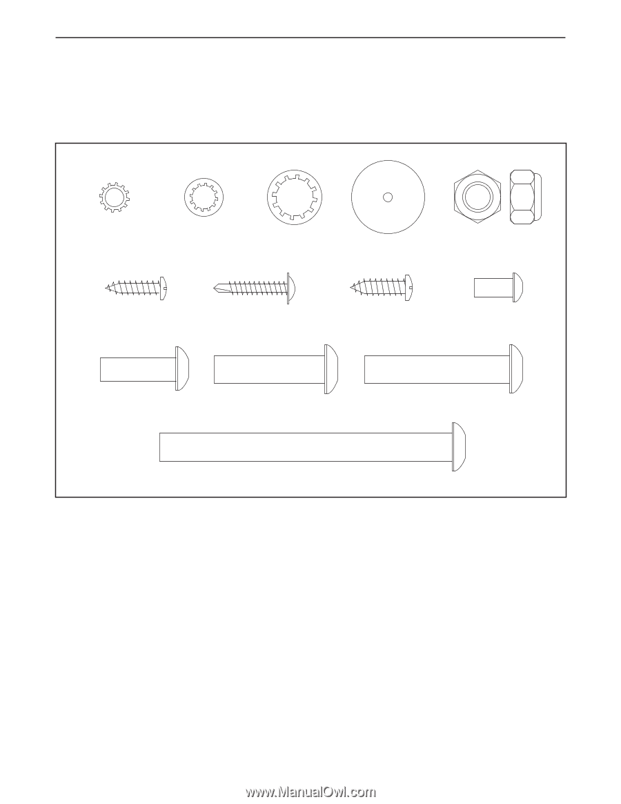
PART IDENTIFICATION CHART Use the drawings below to identify small parts used for assembly. The number in parentheses below each drawing is the key number of the part, from the PART LIST near the end of this manual. The number following the key number is the quantity used for assembly. Note: If a part is not in the hardware kit, check to see if it is preattached. Extra hardware may be included. 1/4" Star Washer (12)-8 5/16" Star Washer (13)-4 3/8" Star Washer (11)-6 Base Foot Spacer (94)-2 3/8" Nut (10)-5 #8 x 3/4" Screw (1)-6 #8 x 1" Tek Screw (5)-4 #10 x 3/4" Screw (2)-4 1/4" x 1/2" Screw (9)-4 5/16" x 1" Bolt (4)-6 3/8" x 1 1/2" Screw (14)-2 3/8" x 2" Bolt (8)-5 3/8" x 4" Screw (7)-4 6
-
 1
1 -
 2
2 -
 3
3 -
 4
4 -
 5
5 -
 6
6 -
 7
7 -
 8
8 -
 9
9 -
 10
10 -
 11
11 -
 12
12 -
13
-
14
-
15
-
16
-
17
-
18
-
19
-
20
-
21
-
22
-
23
-
24
-
25
-
26
-
27
-
28
-
29
-
30
-
31
-
32
-
33
-
34
-
35
-
36
 |
 |
6
Base Foot
Spacer (94)–2
#8 x 3/4" Screw
(1)–6
3/8" Star
Washer (11)–6
#8 x 1" Tek Screw
(5)–4
3/8" Nut (10)–5
5/16" Star
Washer (13)–4
#10 x 3/4" Screw
(2)–4
3/8" x 4" Screw (7)–4
5/16" x 1"
Bolt (4)–6
3/8" x 2" Bolt (8)–5
3/8" x 1 1/2" Screw (14)–2
1/4" x 1/2"
Screw (9)–4
1/4" Star
Washer (12)–8
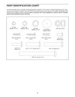
PART IDENTIFICATION CHART
Use the drawings below to identify small parts used for assembly. The number in parentheses below each draw-
ing is the key number of the part, from the PART LIST near the end of this manual. The number following the key
number is the quantity used for assembly.
Note: If a part is not in the hardware kit, check to see if it is preat-
tached. Extra hardware may be included.