ProForm Xp 300 Weight Bench Exerciser English Manual - Page 12
Barbell Guides.
 |
View all ProForm Xp 300 Weight Bench Exerciser manuals
Add to My Manuals
Save this manual to your list of manuals |
Page 12 highlights
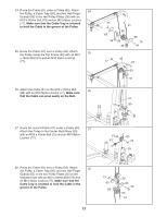
20. Orient the Locking Bar (50) as shown. Slide the 20 Barbell (51) through the Left Barbell Guide (52), the Locking Bar, and the Right Barbell Guide (53). 53 Make sure that the Barbell is centered in the Barbell Guides. Engage the Locking Bar into the Uprights (43) at the lowest position. 50 21. Handtighten an M8 x 20mm Button Screw (16) 21 into the Left Barbell Guide (52). Slide a Weight Stop (69) onto the Barbell (51). Handtighten an M6 x 15mm Button Screw (17) into the Weight Stop. Make sure that the Screw is tightened enough to engage the hole (see drawing 20) in the Barbell. Repeat this step on the other side of the Barbell (51). Tighten the screws used in this step, and the bolts and locknuts used in steps 11-15 and 17-19. Press two Center Base Feet (60) onto the Center Rack Base (39). Press the Rear Upright Foot (59) onto the Rear Upright (41). Press two Front Upright Feet (64) onto the Front Uprights (43). 22 22. Route a Cable (61) up through the Top Frame (45) and over a Pulley (63). Attach the Pulley inside the Top Frame with an M10 x 67mm Bolt (86), two M10 Washers (80), two 16mm x 12.5mm Spacers (76), and an M10 Nylon Locknut (77). 23. Route the Cable (61) over a Pulley (63) and down 23 through the Top Frame (45). Attach the Pulley inside the Top Frame with an M10 x 67mm Bolt (86), two M10 Washers (80), two 16mm x 12.5mm Spacers (76), and an M10 Nylon Locknut (77). Hole 52 43 51 60 52 43 51 16 41 59 39 60 17 69 64 45 80 63 77 76 61 76 80 86 63 80 76 45 77 61 76 80 86 12
-
 1
1 -
2
-
3
-
4
-
5
-
6
-
 7
7 -
 8
8 -
 9
9 -
 10
10 -
 11
11 -
 12
12 -
 13
13 -
 14
14 -
 15
15 -
 16
16 -
 17
17 -
18
-
19
-
20
-
21
-
22
-
23
-
24
 |
 |
