Reebok Rel 8 Elliptical English Manual - Page 8
Apply grease to the Arm Axle 34. Insert the Arm Axle
 |
View all Reebok Rel 8 Elliptical manuals
Add to My Manuals
Save this manual to your list of manuals |
Page 8 highlights
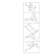
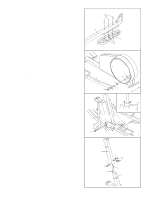
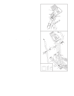
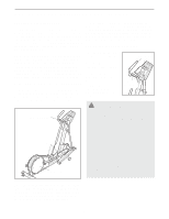
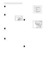
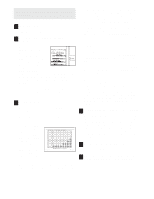
9. Remove the four Console Screws (35) and the four Console Washers (101) from the Console (87). Connect the Extension Harness (99) and the Pulse Wires (103) to the corresponding console wires. Attach the ground wire to the Upright (2) with an M4 x 16mm Screw (72). Attach the Console (87) to the Upright (2) with the four Console Screws (35) and the four Console Washers (101) removed previously. Be careful to avoid pinching the wires. 9 87 Console Wires 99 103 101 Ground Wire 72 10. Slide the Left Upper Body Arm (15), which is marked with an "L" sticker, onto the Chrome Tube (98) on the Left Pedal Arm (3). Slide the Right Upper Body Arm (18) onto the Chrome Tube on the Right Pedal Arm (4). Make sure that the Upper Body Arms are on the correct sides-the upper ends should bend in the direction shown by the arrows. Next, slide an Axle Cover (49) onto the post on each Upper Body Arm. Apply grease to the Arm Axle (34). Insert the Arm Axle into the Upright (2), the right Pivot Cover (49), and the Right Upper Body Arm (18) as shown. Push the Arm Axle into the Upright until the left end of the Axle is flush with the left side of the Upright. Next, raise the Left Upper Body Arm (15) and insert the Arm Axle into the left Axle Cover (49) and the Left Upper Body Arm. Center the Arm Axle. Using the included pedal tool, tap two Push Nuts (94) about 1/8" onto each end of the Arm Axle (34). Make sure that the Push Nuts are turned as shown in the inset drawing. Note: It may be helpful if another person holds a block of wood against one end of the Arm Axle while you tap Push Nuts onto the other end. Press the two Axle Caps (51) onto the Arm Axle (34). 2 35 35 10 49 2 34 15 49 51 94 Grease Post 98 Pedal Tool 94 34 3 18 51 94 98 4 11. Make sure that all parts of the elliptical crosstrainer are properly tightened. Note: Some hardware may be left over after assembly is completed. To protect the floor or carpet from damage, place a mat under the elliptical crosstrainer. 8
-
 1
1 -
2
-
 3
3 -
 4
4 -
 5
5 -
 6
6 -
 7
7 -
 8
8 -
 9
9 -
 10
10 -
 11
11 -
 12
12 -
 13
13 -
14
-
15
-
16
-
17
-
18
-
19
-
20
-
21
-
22
-
23
-
24
 |
 |
