Rheem P-M406 Operating Instructions - Page 19
Ansi Z223.1 Canada - Can/csa-b149., Ansi Z223.1 Canada - Can/csa, B149., Gas Supply Connections,
 |
View all Rheem P-M406 manuals
Add to My Manuals
Save this manual to your list of manuals |
Page 19 highlights
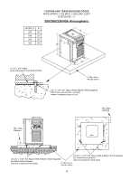
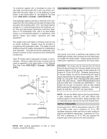
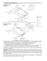
For protection against rain or blockage by snow, the vent pipe must terminate with a vent cap which complies with the local codes or, in the absence of such codes, to the latest edition of the National Fuel Gas Code, ANSI Z223.1 (Canada - CAN/CSA-B149). GAS SUPPLY CONNECTIONS The discharge opening must be a minimum of 2 ft vertically from the roof surface and at least 2 ft higher than any part of the building within 10 ft. Vent stack shall be at least 5 ft in vertical height above the drafthood outlet. The vent cap location shall have a minimum clearance of 4 ft horizontally from, and in no case below, unless a 4 ft horizontal distance is maintained, from electric meters, gas meters, regulators and relief equipment. The weight of the vent stack or chimney must not rest on heater drafthood. Support must be provided in compliance with applicable codes. The heater top and drafthood must be readily removable for maintenance and inspection. Vent pipe should be adequately supported to maintain proper clearances from combustible construction. Type "B" double-wall or equivalent vent pipe is recommended. However single-wall metal vent pipe may be used as specified in the latest edition of the National Flue Gas Code ANSI Z223.1 (Canada - CAN/CSAB149). 10' OR LESS 2' MIN VENT PIPE VENT CAP 2' MIN 5' MIN DRAFT HOOD HEATER Gas piping must have a sediment trap ahead of the heater gas controls, and a manual shut-off valve located outside the heater jacket. All gas piping should be tested after installation in accordance with local codes. CAUTION: The heater and its manual shut-off valve must be disconnected from the gas supply during any pressure testing of that system at test pressures in excess of 1/2 psi (3.45 kPa). Dissipate test pressure in the gas supply line before reconnecting the heater and its manual shut off valve to gas supply line. FAILURE TO FOLLOW THIS PROCEDURE MAY DAMAGE THE GAS VALVE. OVER PRESSURIZED GAS VALVES ARE NOT COVERED BY WARRANTY. The heater and its gas connections shall be leak tested before placing the appliance in operation. Use soapy water for leak test. DO NOT use open flame. NOTE: Do not use Teflon tape on gas line pipe thread. A pipe compound rated for use with natural and propane gases is recommended. Apply sparingly only on male pipe ends, leaving the two end threads bare. SUPPLY PRESSURES A minimum of 6 in. WC for atmospheric units (5 in. WC for Lo NOx units), and a maximum of 14 in. WC upstream pressure under load and no-load conditions must be provided for natural gas. A minimum of 12 in. WC and a maximum of 14 in. WC are required for propane gas under load and no-load conditions. NOTE: With venting application of two or more heaters, contact the factory. 19
-
 1
1 -
2
-
3
-
4
-
5
-
6
-
7
-
8
-
9
-
10
-
11
-
12
-
13
-
 14
14 -
 15
15 -
 16
16 -
 17
17 -
 18
18 -
 19
19 -
 20
20 -
 21
21 -
 22
22 -
 23
23 -
 24
24 -
25
-
26
-
27
-
28
-
29
-
30
-
31
-
32
-
33
-
34
-
35
-
36
-
37
-
38
-
39
-
40
-
41
-
42
-
43
-
44
-
45
-
46
-
47
-
48
-
49
-
50
-
51
-
52
-
53
-
54
-
55
-
56
 |
 |
