Rheem P-M406 Operating Instructions - Page 41
Unitherm Governor U.g. Replacement
 |
View all Rheem P-M406 manuals
Add to My Manuals
Save this manual to your list of manuals |
Page 41 highlights
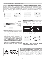
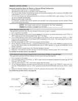
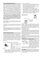
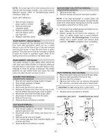
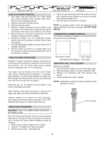
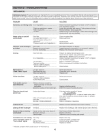
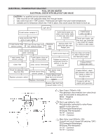
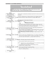
UNITHERM GOVERNOR (U.G.) REPLACEMENT 1. Shut water, gas and electricity off, close valves and relieve pressure. 2. Drain heat exchanger. 3. Remove retainer plug located next to the outlet pipe connection. 4. Unsnap old U.G. to remove from retainer plug. Snap in new U.G. 5. Reinstall retainer plug, taking care to lubricate gasket with a non-petroleum based grease such as AquaLube. Retainer Plug Spring U.G. Gasket To test the operation of the Unitherm Governor, place in hot water (over 110°F) and watch for movement against spring. If there is no movement, replace unit. LO NOx POOL HEATERS The Lo NOx pool heaters are certified and tested under the ANSI Z21.56/CSA 4.7 Standard for GasFired Pool Heaters. The heater should be installed to meet all local codes, and the latest editions of the National Fuel Gas Code Z223.1 and the National Electrical Code, ANSI/NFPA 70. OPERATION On call for heat, the ignition system, consisting of an electronic spark module, gas valve and pilot system, is energized. Providing the pilot is proven, the blower will start running, the main gas valve will open and the heater will operate. When the operating control is satisfied the heater will shut down. START-UP PROCEDURES 1. Turn on power to the heater with gas supply off. 2. Turn on gas supply. 3. Set controller to call for heat. 4. System should start as follows: a. Spark will turn on, pilot gas valve will open, and the blower will begin running. b. Once the blower provides pressure, the main gas valve will open. c. Heater will operate until call for heat is satisfied. NOTE: Door must be in place for proper operation. deck under cold-start conditions. After about five minutes of operation, the flames should settle down and blue tips should become visible. Lifting of flames beyond five minutes would indicate too much combustion air. VISUAL INSPECTION Flames can be observed through the opening below the plenum. Flame color is blue and evenly spread on the top surface of the burner. At least every three months a visual inspection should be made of the burners. ELECTRICAL Be sure that electrical service to the heater has proper overload fuse or circuit breaker protection, wire size and connections which comply with all applicable codes. FLAME ROLL-OUT SAFETY SWITCH Lo NOx heaters are equipped with a thermal cut-off device to prevent flame roll-out in the event the heat exchanger becomes blocked. It is a "manual reset" type roll-out switch that must be reset by a service technician after any over-temperature conditions have been fixed. Excessive restriction in the heat exchanger flue passage may cause the switch to disable the heater. BLOWER ADJUSTMENT This Lo NOx pool heater is equipped with a combustion air plate (baffle) mounted on the air intake to the combustion air blower. The baffle has a hole that is utilized to control the air inlet to the blower. When the combustion air setting is proper, there will be some lifting of the flames on some areas of the burner Manual Reset Switch 41
-
 1
1 -
2
-
3
-
4
-
5
-
6
-
7
-
8
-
9
-
10
-
11
-
12
-
13
-
14
-
15
-
16
-
17
-
18
-
19
-
20
-
21
-
22
-
23
-
24
-
25
-
26
-
27
-
28
-
29
-
30
-
31
-
32
-
33
-
34
-
35
-
 36
36 -
 37
37 -
 38
38 -
 39
39 -
 40
40 -
 41
41 -
 42
42 -
 43
43 -
 44
44 -
 45
45 -
 46
46 -
47
-
48
-
49
-
50
-
51
-
52
-
53
-
54
-
55
-
56
 |
 |
