Rheem P-M406 Operating Instructions - Page 39
PILOT SAFETY - AFT Models
 |
View all Rheem P-M406 manuals
Add to My Manuals
Save this manual to your list of manuals |
Page 39 highlights
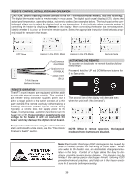
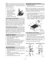
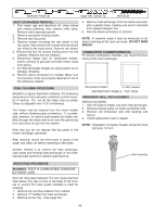
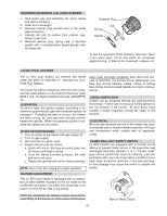
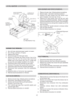
NOTE: An erratic high limit is often characteristic of an internal heat exchanger problem, e.g. scale build-up, defective bypass. Refer to Troubleshooting section (starting on page 43). HIGH LIMIT REMOVAL 1. Shut off main electrical power switch to heater. 2. Remove inlet/outlet inspection panel. 3. Remove defective high limit and replace with a new high limit. 4. Replace inspection panel. PILOT SAFETY - Millivolt Models Heaters equipped with the standing pilot (millivolt system) have pilot generators which act as a safety device to shut off the flow of gas to the main burners and the pilot burner in case the pilot flame is extinguished. The pilot burner must be manually re-lighted to place the heater in operation again. Refer to the lighting instructions provided on the heater label. PILOT SAFETY - AFT Models The heater employs a pilot safety which closes the main gas valve within 8/10ths of a second whenever the pilot flame is interrupted. The pilot flame is automatically lit when the device is powered. The heater performs its own safety check and opens the main valve only after the pilot is proven to be lit. BURNER TRAY REMOVAL ATMOSPHERIC MODELS 1. Shut off main electrical power switch to heater. 2. Shut off gas upstream of heater. 3. Remove front door. 4. Disconnect gas line from gas valve. 5. Remove (2) screws that mount burner tray to unit, and (2) screws that secure gas valve to jacket. 6. Disconnect wires that terminate at gas valve. 7. Disconnect hi-tension wire from PC board. 8. Slide out burner tray. 9. Reverse above procedure to reinstall. MAIN BURNER AND ORIFICE REMOVAL ATMOSPHERIC MODELS 1. Remove burner tray. 2. Remove screws and burner hold-down bracket. NOTE: If the heat exchanger is sooted badly, the burner hold-down bracket and spacer can become distorted from direct-flame impingement and this usually necessitates replacement of these parts. 3. Lift burners from slotted spacers and slide from orifices. Clean with a wire brush. 4. Orifices usually do not need to be replaced. To clean, run either copper wire or wood toothpick through orifice. Do not enlarge hole. To remove orifice, use a socket wrench and remove from manifold. DO NOT overtighten when reinstalling. GAS VALVE PILOT BURNER BURNER HOLD-DOWN BRACKET GAS ORIFICE 206-406 Atmospheric PILOT REMOVAL AND CLEANING 1. Disconnect pilot tubing and wires from gas valve. 2. Remove pilot assembly from burner tray. 3. Remove pilot from bracket. 4. Remove pilot orifice and air opening (Honeywell MV unit only), and clean with wire or small brush. CAUTION! Do not enlarge hole in pilot orifice. 5. Reverse above procedure to reinstall. HONEYWELL MILLIVOLT PILOT ROBERTSHAW MILLIVOLT PILOT GAS VALVE REMOVAL ATMOSPHERIC MODELS 1. Shut off gas supply to the heater. Remove gas piping to gas valve inlet. 2. Disconnect wires, pilot tubing and bleed line, if required. 3. Remove burner tray from heater. 4. Turn vertical gas pipe from manifold slightly and unscrew gas valve. 5. Reverse above procedure to reinstall. Pilot Air Opening Orifice Pilot Orifice 39
-
 1
1 -
2
-
3
-
4
-
5
-
6
-
7
-
8
-
9
-
10
-
11
-
12
-
13
-
14
-
15
-
16
-
17
-
18
-
19
-
20
-
21
-
22
-
23
-
24
-
25
-
26
-
27
-
28
-
29
-
30
-
31
-
32
-
33
-
 34
34 -
 35
35 -
 36
36 -
 37
37 -
 38
38 -
 39
39 -
 40
40 -
 41
41 -
 42
42 -
 43
43 -
 44
44 -
45
-
46
-
47
-
48
-
49
-
50
-
51
-
52
-
53
-
54
-
55
-
56
 |
 |
