Rheem P-M406 Operating Instructions - Page 3
Contents - he
 |
View all Rheem P-M406 manuals
Add to My Manuals
Save this manual to your list of manuals |
Page 3 highlights
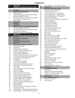
CONTENTS 4 PART ONE 30 Wiring Diagram - AFT Models, Lo NOx OWNER'S OPERATING INSTRUCTIONS 31 SECTION 4 SERVICING INSTRUCTIONS 4 SECTION 1 31 General Location of Controls START-UP PROCEDURES 32 Control Panel Removal 4 Before Start-Up 32 Control Adjustments - AFT Models 5 Lighting Instructions & Shut-Off Procedures - 32 Control Adjustments - Millivolt Models Manually Lighted Pilots MV 33 Thermostat Operation - AFT Board 6 Operating Instruction & Shut-Off Procedures - 35 Status and Diagnostics Automatically Lighted Pilots IID 36 Remote Control Installation and Operation 7 After Start-Up 36 Remote Operation 7 SECTION 2 36 Activating the Remote CAUTION 37 Remote Control Wiring 8 SECTION 3 37 2-Wire Remote Control MAINTENANCE & CARE PROCEDURES 37 3-Wire Remote Control 8 Pool & Spa Water Chemistry 38 Time Clock / Fireman's Switch 8 Automatic Chlorinators & Chemical Feeders 38 Water Pressure Switch 9 Cold Weather Operation 38 Flame Roll-Out Safety Switch 9 Winterizing the Pool & Spa Heater 38 High Limits 10 PART TWO 39 Pilot Safety INSTALLATION & SERVICE INSTRUCTIONS 39 Burner Tray Removal (ATM) 10 SECTION 1 39 Gas Valve Removal (ATM) RECEIVING EQUIPMENT 39 Main Burner and Orifice Removal (ATM) 11 SECTION 2 39 Pilot Removal and Cleaning GENERAL SPECIFICATIONS 40 Heat Exchanger Removal 11 SECTION 3 40 Tube Cleaning Procedure INSTALLATION INSTRUCTIONS 40 Desooting Procedure 11 Code Requirements 40 Combustion Chamber Removal 12 Clearances 40 Immersion Well Replacement 12 Outdoor Heater Installation 41 Unitherm Governor (U.G.) Replacement 14 Florida and Texas Building Codes 41 Lo NOx Pool Heaters 15 Indoor Heater Installation 41 Operation 15 Outdoor Stack/Indoor Stack 41 Start-Up Procedures 16 Atmospheric Specifications and Dimensions 41 Visual Inspection 17 Lo NOx Specifications and Dimensions 41 Electrical 18 Combustion and Ventilation Air 41 Flame Roll-Out Safety Switch 18 Vent Piping 42 Burner Tray Removal 19 Gas Supply Connections 42 Gas Valve Removal 20 Gas Pressure Regulator 42 Main Burner and Orifice Removal 20 Gas Pressure Adjustment Locations 42 Pilot Removal 20 Pipe Sizing For Gas Connections 42 Combustion Blower Removal 21 Flow Rates 43 SECTION 5 21 Heat Exchanger Pressure Drop Tables TROUBLESHOOTING 22 Polymer Headers 43 Mechanical 22 Cast Iron Headers 44 Electrical - Standing Pilot Millivolt 22 Unitherm Governor Operation 45 Electrical - Electronic Ignition (IID) 23 Internal Automatic Bypass Valve 46 Control Logic - Flow Chart 23 External Auxiliary Bypass Valve 47 SECTION 6 23 Auxiliary Bypass Valve Adjustment REPLACEMENT PARTS 23 Pressure Relief Valve Installation 48 Illustrated Parts List 24 Plumbing-Water Connections 51 Part Numbers 25 Heat Exchanger Reversal Procedure 26 Electrical Wiring 26 Millivolt Models 26 Advanced Flame Technology (AFT) Models 27 Transformer Wiring 28 Wiring Diagram - Millivolt (Mechanical Therm.) 29 Wiring Diagram - AFT Models, Atmospheric 3
-
 1
1 -
 2
2 -
 3
3 -
 4
4 -
 5
5 -
 6
6 -
 7
7 -
 8
8 -
 9
9 -
10
-
11
-
12
-
13
-
14
-
15
-
16
-
17
-
18
-
19
-
20
-
21
-
22
-
23
-
24
-
25
-
26
-
27
-
28
-
29
-
30
-
31
-
32
-
33
-
34
-
35
-
36
-
37
-
38
-
39
-
40
-
41
-
42
-
43
-
44
-
45
-
46
-
47
-
48
-
49
-
50
-
51
-
52
-
53
-
54
-
55
-
56
 |
 |
