Ridgid JP0610 Owners Manual - Page 12
Features, Tools Needed - jointer planer
 |
View all Ridgid JP0610 manuals
Add to My Manuals
Save this manual to your list of manuals |
Page 12 highlights
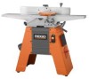
FEATURES KNOW YOUR JOINTER/PLANER See Figure 6. Before attempting to use this product, familiarize yourself with all operating Features and Safety Rules. DUST CHUTE WITH TOOL STORAGE Allows 4 in. diameter dust collection hose. Easily slides up and out of the way when a vacuum is not connected. Also tool storage for knife adjustment wrenches. OUTFEED TABLE The section of a jointer bed which supports the workpiece after it passes over the cutter. FENCE LOCK KNOB Allows fence to move across table front to back. This is done to achieve full width of cut or to use a different (sharper) part of cutter knives. PULLEY GUARD Protects user from incidental access to the motor belt and pulley. TABLE LOCK SCREW Use these screws to lock infeed or outfeed table at a desired height. DEPTH OF CUT HANDWHEEL By turning the handwheel you can control how much wood will be removed from the workpiece on each cut. 90° AND 135° FENCE STOPS When adjusted properly, these stops provide a method for quickly moving the fence to a 90° or 135° position from the table. TOOLS NEEDED FENCE TILT HANDLE Assists in positioning the fence to various bevel angles. FENCE Guides workpiece over cutter head. BEVEL LOCK HANDLE Secures the fence at the desired bevel setting. INFEED TABLE The section of the jointer bed upon which the workpiece is placed before being pushed into the cutter. Its height is adjustable which allows the operator to select the depth of cut. CUTTER GUARD Helps protect the operator from the sharp knives on the cutter head. It is spring loaded so it automatically keeps the cutter head covered before, during, and after a cutting operation. It must always be used. STOP PIN For rabbeting operations up to 1/2 in. deep, stop pin can be pulled out to lower infeed table in 1/8 in. increments. ANGLE GAUGE Used to set the fence at the desired bevel angle. ON/OFF SWITCH Turns the tool on and off. When the key is inserted in the switch lever, the power may be turned ON ( I ) and OFF ( O ). When it is removed, the power cannot be turned ON. This feature is intended to help prevent any unauthorized use. The following tools (not included) are needed for making adjustments or installing the knives: PHILLIPS SCREWDRIVER STRAIGHT EDGE ADJUSTABLE WRENCH OPEN END WRENCH (1/2 IN.) COMBINATION SQUARE Fig. 7 12
-
 1
1 -
2
-
3
-
4
-
5
-
6
-
 7
7 -
 8
8 -
 9
9 -
 10
10 -
 11
11 -
 12
12 -
 13
13 -
 14
14 -
 15
15 -
 16
16 -
 17
17 -
18
-
19
-
20
-
21
-
22
-
23
-
24
-
25
-
26
-
27
-
28
-
29
-
30
-
31
-
32
-
33
-
34
-
35
-
36
-
37
-
38
-
39
-
40
 |
 |
