Ridgid JP0610 Owners Manual - Page 31
Using Angle Gauge, Adjusting Table Extension, Adjusting Guard Spring - fence assembly
 |
View all Ridgid JP0610 manuals
Add to My Manuals
Save this manual to your list of manuals |
Page 31 highlights
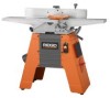
ADJUSTMENTS USING ANGLE GAUGE See Figure 44. An angle gauge is included with the RIDGID jointer to set the fence at the proper angle. To assemble the gauge slide the one side over the other at right angles to each other. The angle gauge has several faces for some of the more common angle settings. These angles include 90°, 45°, 30°, and 22.5°. There is also a 0°-45° protractor on one side to set the fence to an angle not provided. Simply set the gauge at the end of the fence on the outfeed table as shown and set the angle you need. ADJUSTING TABLE EXTENSION See Figure 45. The table extension is adjusted at the factory and should not require any additional adjustments. In the event that it shifted during shipping, align it to the outfeed table as follows. n Loosen the hex head screws that attach the extension to the outfeed table. n Using a straight edge, align the extension to be flush with the outfeed table. n Tighten the hex head screws and recheck the alignment. ADJUSTING GUARD SPRING See Figure 46. n Remove the pan head screw from bottom of the cutter head guard post. NOTE: The cutter guard stop post limits the amount of cutter guard travel. Never modify the stop post or remove cutter guard before any operation. n Remove tension on cutter head guard by turning tension knob clockwise. Pull up on cutter head guard to remove. n Add tension to the cutter head guard in 1/2 turn increments by turning the tension knob and reinserting the guard post. n Repeat Cutter Head Guard Functional Check as previously described. NOTE: Do not overtighten the spring. Overtightening may cause premature spring or guard breakage. If the guard or spring breaks or malfunctions, do not use the tool. Replace the defective parts before the tool is put back in service. n When the adjustment is complete, reinstall the pan head screw in the bottom of the guard post. EXTENSION SLOT PAN HEAD SCREW CUTTER GUARD STOP POST � CUTTER GUARD ANGLE GAUGE Fig. 44 OUTFEED TABLE SOCKET HEAD SCREW EXTENSION EVEN WITH OUTFEED TABLE Fig. 45 TOP VIEW GUARD SPRING 18 1 4 3 8 1DE2PTH OF CUT KNOB COUNTERCLOCKWISE 31 Fig. 46
-
 1
1 -
2
-
3
-
4
-
5
-
6
-
7
-
8
-
9
-
10
-
11
-
12
-
13
-
14
-
15
-
16
-
17
-
18
-
19
-
20
-
21
-
22
-
23
-
24
-
25
-
 26
26 -
 27
27 -
 28
28 -
 29
29 -
 30
30 -
 31
31 -
 32
32 -
 33
33 -
 34
34 -
 35
35 -
 36
36 -
37
-
38
-
39
-
40
 |
 |
