Ridgid JP0610 Owners Manual - Page 18
Assembling Rear Panel, Assembling And Tensioning Belt, Assembling The Pulley Guard, Warning
 |
View all Ridgid JP0610 manuals
Add to My Manuals
Save this manual to your list of manuals |
Page 18 highlights
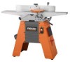
ASSEMBLY ASSEMBLING REAR PANEL See Figure 18. n Locate the following: Carriage Head Bolts (6), 5/16-18 x 1/2 in. Hex Nuts Serrated Flange (6), 5/16 in. Rear Cabinet Panel (1) NOTE: Tabs on rear panel must be on the inside of side panels prior to securing with nuts and bolts. n Position the rear panel in place from the bottom of the cabinet as shown. Bolt in place using 5/16 in. carriage head bolts and 5/16 in. flange nuts. Make sure the rear panel's tabs are on the inside of the cabinet. Tighten the nuts. n Thread the power cord through the hole in the rear of the cabinet. n Remove the screws and washers from the cable plate. n Thread the power cord through the hole from the inside of the cabinet until the cord plate reaches the cabinet. n Reinstall the washers and screws from the outside of the cabinet with the cord plate flush against the inside of cabinet. Retighten screws. NOTE: Securely tighten all cabinet nuts and bolts as well as jointer table mounting bolts at this time. ASSEMBLING AND TENSIONING BELT See Figure 19. n Locate the V-belt. n Slip the V-belt over both the motor and cutter head pulleys. n While the jointer is still upside down, slide the motor up the motor mount to put tension on the V-belt. This will require assistance. Once the V-belt has been tensioned, tighten the motor bolts. The V-belt should have approximately 1 in. deflection (the measurement of how much you can push in on one side of the V-belt). NOTE: An alternate method for tensioning the V-belt is to turn the unit upright, letting the motor slide down in the slots and allowing the weight of the motor only to tension the V-belt. n Visually check the front to back alignment of the pulleys and adjust the motor as needed. ASSEMBLING THE PULLEY GUARD See Figure 20. n Locate the following: Cross Serrated Pan Head Screws (4), 3/16-24 x 3/8 in. Pulley guard (1) n With assistance, set the jointer upright. WARNING: This tool is heavy. To avoid back injury, lift with your legs, not your back, and get help when needed. n Mount the pulley guard in place as shown using 3/16 in. screws. V-BELT PAN HEAD SCREW 18 REAR PANEL CABINET Fig. 18 SLOTS 1 IN. BELT DEFLECTION Fig. 19 PULLEY GUARD Fig. 20
-
 1
1 -
2
-
3
-
4
-
5
-
6
-
7
-
8
-
9
-
10
-
11
-
12
-
 13
13 -
 14
14 -
 15
15 -
 16
16 -
 17
17 -
 18
18 -
 19
19 -
 20
20 -
 21
21 -
 22
22 -
 23
23 -
24
-
25
-
26
-
27
-
28
-
29
-
30
-
31
-
32
-
33
-
34
-
35
-
36
-
37
-
38
-
39
-
40
 |
 |
