Ridgid RP 330-C Owners Manual - Page 11
Maintenance Instructions
 |
View all Ridgid RP 330-C manuals
Add to My Manuals
Save this manual to your list of manuals |
Page 11 highlights
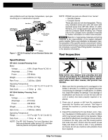
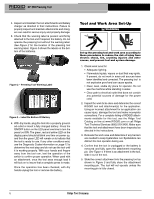
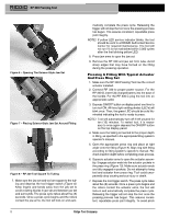
RP 330 Pressing Tool point injuries, keep fingers away from actuator and press ring during the press cycle. Pressure Release Button Figure 9 - Installing Press Ring Onto Fitting Figure 10 - Attaching Actuator to Press Ring NOTE! If yellow LED service indicator blinks, the tool should be sent to a RIDGID Authorized Service Center for required maintenance. The tool will not run if it is not maintained within 2,000 cycles after the first blinking yellow LED. 8. After cycle is complete, squeeze actuator arms to open and separate actuator from press ring. Remove the press ring from fitting by manually grasping ring halves and opening assembly. Avoid any sharp edges which may have formed on fitting during pressing operation. NOTICE The RP 330 Pressing Tool will turn off automatically if the battery is too low to successfully complete a pressed connection. This will be indicated by blinking of the green LED. A fully charged battery should be inserted in the tool and the pressed connection should be repeated as indicated above. To retract the rollers and remove the tool from the fitting if battery dies or tool malfunctions during pressed connection, it is necessary to press the black pressure release button on the left hand side of the tool. (Figure 11) Figure 11 - Pressure Release Button Inspecting The Pressed Connection 1. Inspect the pressed fitting. If the fitting is supplied with a control ring and/or a control label by the fitting manufacturer, remove it. Control rings and label are supplied by the manufacturer to indicate that the fitting has not yet been pressed. Removal of the control ring and label indicates to others that the connection has been pressed. Look for the following: • Excessive misalignment of the tubes. Note that a slight amount of misalignment at the pressed connection is considered normal. • Tubes that are not fully inserted into the fitting - double check the insertion marks made on the tube to see that they are still aligned with the end of the fitting. • Incorrect jaw or ring alignment with the fitting contour, distorted or deformed fitting. • Any other issues per the fitting manufacturer. If any of these problems are found, then removal of the fitting is required and a new fitting and tube will need to be prepared and pressed in its place. 2. Test system in accordance with normal practice and local codes. 3. See press system's operator's manual for specific inspection criteria. Maintenance Instructions WARNING Make sure cord is unplugged or battery is removed from tool before performing maintenance or making any adjustment. Ridge Tool Company 9
-
 1
1 -
2
-
3
-
4
-
5
-
 6
6 -
 7
7 -
 8
8 -
 9
9 -
 10
10 -
 11
11 -
 12
12 -
 13
13 -
 14
14 -
 15
15 -
 16
16 -
17
-
18
-
19
-
20
-
21
-
22
-
23
-
24
-
25
-
26
-
27
-
28
-
29
-
30
-
31
-
32
-
33
-
34
-
35
-
36
-
37
-
38
-
39
-
40
-
41
-
42
-
43
 |
 |
