Ryobi A18MS01G Operation Manual
Ryobi A18MS01G Manual
 |
View all Ryobi A18MS01G manuals
Add to My Manuals
Save this manual to your list of manuals |
Ryobi A18MS01G manual content summary:
- Ryobi A18MS01G | Operation Manual - Page 1
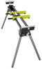
MITER SAW STAND STAND POUR SCIE À ONGLETS PEDESTAL PARA SIERRA INGLETEADORA A18MS01 / A18MS01G Your miter saw stand has been engineered and manufactured to our high standard for dependability, ease of operation, and operator safety. When properly cared for, it will give you years of rugged, trouble - Ryobi A18MS01G | Operation Manual - Page 2
handle and properly support the workpiece. Follow the tool mounting instructions carefully, and ensure the tool is fastened securely. Maximum weight of the miter saw and workpiece together must not exceed 400 pounds. Do not apply an unbalanced load that could cause the miter saw stand to tip - Ryobi A18MS01G | Operation Manual - Page 3
. SYMBOL NAME DESIGNATION/EXPLANATION Safety Alert Precautions that involve your safety. Read The Operator's Manual To reduce the risk of injury, user must read and understand operator's manual before using this product. Eye Protection Always wear eye protection with side shields marked to - Ryobi A18MS01G | Operation Manual - Page 4
WORK STOP FEATURES SAW MOUNTING BRACKET WORK SUPPORT WORK SUPPORT WORK SUPPORT MOUNTING BRACKET WORK STOP EXTENSION RAIL WORK SUPPORT MOUNTING BRACKET EXTENSION RAIL Fig. 1 4 - English - Ryobi A18MS01G | Operation Manual - Page 5
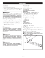
parts on the Packing List are already assembled to your product when you unpack it. Parts Miter Saw Stand Saw Mounting Brackets (2) Work Supports (2) Work Support Mounting (4) Nuts (4) Operator's Manual Warranty Registration Card PREPARING THE STAND See Figure 2. n Lay the stand's top surface down on - Ryobi A18MS01G | Operation Manual - Page 6
down position. n Place a 2 x 4 or similar type of stable support underneath the saw to raise the saw and allow access to the saw's mounting feet. n Place a saw mounting bracket underneath the raised side of the saw, aligning the mounting holes on the miter saw base with the slot in the top of the - Ryobi A18MS01G | Operation Manual - Page 7
included). n Drill holes in the mounting surface to match the slots in the saw mounting brackets. n Proceed with installation as previously described. NUT LOCK WASHER FLAT WASHER NUT LOCK WASHER FLAT WASHER MITER SAW MOUNTING SURFACE SAW MOUNTING BRACKET CARRIAGE BOLT SLOT 7 - English Fig. 7 - Ryobi A18MS01G | Operation Manual - Page 8
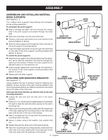
ASSEMBLY MOUNTING THE MITER SAW TO THE STAND See Figures 8 - 9. n Lift the saw and bracket assembly, allowing the assembly to tilt slightly toward your body. n While still tilted toward you, hook the front edge of the bracket assembly onto the front rail of the stand. WARNING: To avoid serious - Ryobi A18MS01G | Operation Manual - Page 9
can result in serious personal injury. APPLICATIONS You may use this tool for the following purpose: To provide a stable, secure work surface for a miter saw USING THE EXTENSION RAILS See Figure 10. Use the extension rails when working with larger workpieces. To extend the rails: n Loosen the - Ryobi A18MS01G | Operation Manual - Page 10
servicing, use only identical replacement parts. Use of any other parts Install the bracket on the miter stand rails and lower the SAW MOUNTING BRACKET WRENCH WARNING: Do not at any time let brake fluids, gasoline, petroleumbased products, penetrating oils, etc., come in contact with plastic parts - Ryobi A18MS01G | Operation Manual - Page 11
accessoire est prêté, il doit être accompagné de ces instructions, afin d'éviter un usage incorrect et d'éventuelles blessures. AVERTISSEMENT : Ce stand est conçu pour être utilisé avec toutes les scies à onglet et les scies à onglet coulissantes de Ryobi avec une lame ayant un diamètre inférieur - Ryobi A18MS01G | Operation Manual - Page 12
SYMBOLES Les termes de mise en garde suivants et leur signification ont pour but d'expliquer le degré de risques associé à l'utilisation de ce produit. SYMBOLE SIGNAL SIGNIFICATION DANGER : Indique une situation extrêmement dangereuse qui, si elle n'est pas évitée, aura pour conséquences des - Ryobi A18MS01G | Operation Manual - Page 13
BUTÉE SUPPORT DE TRAVAIL RAIL D'EXTENSION CARACTÉRISTIQUES SUPPORT DE MONTAGE DE LA SCIE ÉQUERRE DE SUPPORT DE PIÈCE BUTÉE SUPPORT DE TRAVAIL ÉQUERRE DE SUPPORT DE PIÈCE RAIL D'EXTENSION Fig. 1 4 - Françias - Ryobi A18MS01G | Operation Manual - Page 14
peuvent créer des conditions dangereuses, risquant d'entraîner des blessures graves. BORDEREAU D'EXPÉDITION Stand pour scie à onglets Supports de montage de la scie (2) Supports de pièce (2) Équerre de support de pièce (2) Butées (2) Bouton de réglage d'extension (M8 x 25 mm) (2) Bouton de réglage - Ryobi A18MS01G | Operation Manual - Page 15
. S'assurer que les boulons ne dépassent pas de la table de la scie. Si la scie comporte des trous qui s'alignent sur les fentes des supports de montage : n Débrancher la scie et verrouiller le bras en position abaissée. n Placer un morceau de montant 2 x 4 ou un objet similaire au-dessous de la - Ryobi A18MS01G | Operation Manual - Page 16
DE SCIE SCIE À ONGLETS 2 x 4 BOULON DE CARROSSIER FENTE Fig. 6 Si la scie comporte des trous qui ne s'alignent pas sur les fentes des supports de montage : n Débrancher la scie et verrouiller le bras en position abaissée. n Monter la scie sur une planche d'au moins 13 mm (1/2 po) d'épaisseur - Ryobi A18MS01G | Operation Manual - Page 17
être engagés sur les rails ou s'ils peuvent en être retirés lorsque les leviers de verrouillage sont abaissés, retirer immédiatement la scie et son support du stand et serrer la vis de réglage, comme décrit à la section Entretien de ce manuel. Le non respect de cet avertissement peut entraîner des - Ryobi A18MS01G | Operation Manual - Page 18
accessoires non recommandés peut entraîner des blessures graves. APPLICATIONS Cet outil peut être utilisé pour l'application ci-dessous : n Procurer un support stable et sûr pour les scies à onglets UTILISATION DES RAILS D'EXTENSION Voir la figure 10. Utiliser les rails d'extension pour le travail - Ryobi A18MS01G | Operation Manual - Page 19
une clé. n Tourner la vis à l'aide d'un tournevis Phillips. Tourner vers la droite pour serrer le support et vers la gauche pour le desserrer. n Installer le support sur les rails du stand et abaisser le levier de verrouillage pour vérifier le réglage. n Une fois la position correcte obtenue serrer - Ryobi A18MS01G | Operation Manual - Page 20
, se requiere la lectura y la comprensión de este manual del operador, el manual del operador correspondiente a la sierra de mesa, así como un diámetro de hoja mayor a 254 mm (10 pulg.) otra que no sea marca Ryobi de 304,8 mm (12 pulg.). Siempre confirme que cualquiera que sea la sierra empleada, est - Ryobi A18MS01G | Operation Manual - Page 21
DENOMINACIÓN/EXPLICACIÓN Alerta de seguridad Indica un peligro posible de lesiones personales. Lea el manual del operador Para reducir el riesgo de lesiones, el usuario debe leer y comprender el manual del operador antes de usar este producto. V A Hz W min no .../min Protección ocular Alerta - Ryobi A18MS01G | Operation Manual - Page 22
TOPE DE LA PIEZA DE TRABAJO SOPORTE DE LA PIEZA DE TRABAJO RIEL DE EXTENSIÓN CARACTERÍSTICAS APOYO DE MONTAJE DE LA SIERRA TOPE DE LA PIEZA DE TRABAJO PLACAS DE MONTAJE DE LOS SOPORTES DE LA PIEZA DE TRABAJO SOPORTE DE LA PIEZA DE TRABAJO PLACAS DE MONTAJE DE LOS SOPORTES DE LA PIEZA DE TRABAJO - Ryobi A18MS01G | Operation Manual - Page 23
sin haber reemplazado todas las piezas. Usar este producto con partes dañadas o faltantes puede causar lesiones serias al operador. 16 x 2 pulg.)] (4) Arandelas planas (4) Arandelas de seguridad (4) Tuercas (4) Manual del operador Tarjeta de registro de garantía PREPARACIÓN DEL PEDESTAL Vea la figura - Ryobi A18MS01G | Operation Manual - Page 24
del soporte de la pieza de trabajo a través del agujero situado en la parte superior de la placa de montaje del soporte de la pieza de trabajo. n n Introduzca una perilla de ajuste de longitud por la abertura situada en la parte inferior del apoyo de montaje del soporte de la pieza de trabajo y apri - Ryobi A18MS01G | Operation Manual - Page 25
ARMADO TUERCA ARANDELA DE SEGURIDAD ARANDELA PLANA APOYO DE MONTAJE DE LA SIERRA SIERRA INGLETEADORA 2 x 4 PERNO DE CARRUAJE RANURA Fig. 6 Si la sierra tiene agujeros que no se alinean con las ranuras de los apoyos de montaje: n Desconecte la sierra y asegure el brazo de la sierra en la posici - Ryobi A18MS01G | Operation Manual - Page 26
del pedestal para separarlos. n Teniendo el conjunto levemente inclinado hacia usted, levante la parte delantera del conjunto para separarlo del riel delantero del pedestal. 1 2 11 10 16 de este manual. La inobservancia de esta advertencia puede causar lesiones corporales serias. 8 - - Ryobi A18MS01G | Operation Manual - Page 27
FUNCIONAMIENTO ADVERTENCIA: No permita que su familarización con las herramientas lo vuelva descuidado. Tenga presente que un descuido de un instante es suficiente para causar una lesión grave. RIEL DE EXTENSIÓN ADVERTENCIA: Siempre póngase protección ocular con protección lateral con la marca de - Ryobi A18MS01G | Operation Manual - Page 28
MANTENIMIENTO ADVERTENCIA: Al dar servicio a la unidad, sólo utilice piezas de repuesto idénticas. El empleo de piezas diferentes puede presentar un peligro o causar daños al producto. ADVERTENCIA: Siempre póngase protección ocular con protección lateral con la marca de cumplimiento de la norma - Ryobi A18MS01G | Operation Manual - Page 29
NOTES / NOTAS 11 - Ryobi A18MS01G | Operation Manual - Page 30
NOTES / NOTAS 12 - Ryobi A18MS01G | Operation Manual - Page 31
NOTES / NOTAS 13 - Ryobi A18MS01G | Operation Manual - Page 32
OPERATOR'S MANUAL / MITER SAW STAND MANUEL D'UTILISATION / STAND POUR SCIE À ONGLETS MANUAL DEL OPERADOR / BANCO PARA SIERRA INGLETEADORA A18MS01 / A18MS01G To request service, purchase replacement parts, locate an Authorized Service Center and obtain Customer or Technical Support: Visit www.
-
 1
1 -
 2
2 -
 3
3 -
 4
4 -
 5
5 -
 6
6 -
 7
7 -
8
-
9
-
10
-
11
-
12
-
13
-
14
-
15
-
16
-
17
-
18
-
19
-
20
-
21
-
22
-
23
-
24
-
25
-
26
-
27
-
28
-
29
-
30
-
31
-
32
 |
 |

OPERATOR’S MANUAL
MANUEL D’UTILISATION
MANUAL DEL OPERADOR
MITER SAW STAND
STAND POUR SCIE À ONGLETS
PEDESTAL PARA SIERRA
INGLETEADORA
A18MS01 / A18MS01G
Cette stand pour scie à onglets a été conçue et fabriquée
conformément à nos strictes normes de fiabilité, simplicité
d’emploi et sécurité d’utilisation. Correctement entretenue, elle
vous donnera des années de fonctionnement robuste et sans
problème.
AVERTISSEMENT :
Pour réduire les risques de
blessures, l’utilisateur doit lire et veiller à bien comprendre le
manuel d’utilisation avant d’employer ce produit.
Merci de votre achat.
Su pedestal para sierra ingleteadora de pintura ha sido diseñado
y fabricado de conformidad con nuestras estrictas normas para
brindar fiabilidad, facilidad de uso y seguridad para el operador.
Con el debido cuidado, le brindará muchos años de sólido y efi-
ciente funcionamiento.
ADVERTENCIA:
Para reducir el riesgo de lesiones,
el usuario debe leer y comprender el manual del operador antes
de usar este producto.
Le agradecemos su compra.
CONSERVER CE MANUEL POUR
FUTURE RÉFÉRENCE
GUARDE ESTE MANUAL PARA
FUTURAS CONSULTAS
SAVE THIS MANUAL FOR FUTURE REFERENCE
Your miter saw stand has been engineered and manufactured to our high standard for dependability, ease of operation, and
operator safety. When properly cared for, it will give you years of rugged, trouble-free performance.
WARNING:
To reduce the risk of injury, the user must read and understand the operator’s manual before using
this product.
Thank you for your purchase.