Ryobi A18MS01G Operation Manual - Page 5
Assembly - parts
 |
View all Ryobi A18MS01G manuals
Add to My Manuals
Save this manual to your list of manuals |
Page 5 highlights
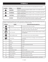
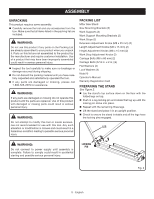
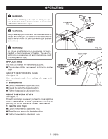
ASSEMBLY UNPACKING This product requires some assembly. n Carefully remove the tool and any accessories from the box. Make sure that all items listed in the packing list are included. WARNING: Do not use this product if any parts on the Packing List are already assembled to your product when you unpack it. Parts on this list are not assembled to the product by the manufacturer and require customer installation. Use of a product that may have been improperly assembled could result in serious personal injury. n Inspect the tool carefully to make sure no breakage or damage occurred during shipping. n Do not discard the packing material until you have carefully inspected and satisfactorily operated the tool. n If any parts are damaged or missing, please call 1-800-525-2579 for assistance. WARNING: If any parts are damaged or missing do not operate this product until the parts are replaced. Use of this product with damaged or missing parts could result in serious personal injury. WARNING: Do not attempt to modify this tool or create accessories not recommended for use with this tool. Any such alteration or modification is misuse and could result in a hazardous condition leading to possible serious personal injury. PACKING LIST Miter Saw Stand Saw Mounting Brackets (2) Work Supports (2) Work Support Mounting Brackets (2) Work Stops (2) Extension Adjustment Knobs (M8 x 25 mm) (2) Length Adjustment Knobs (M8 x 15 mm) (2) Height Adjustment Knobs (M8 x 15 mm) (2) Work Stop Adjustment Knobs (2) Carriage Bolts (M6 x 60 mm) (2) Carriage Bolts (5/16 in. x 2 in.) (4) Flat Washers (4) Lock Washers (4) Nuts (4) Operator's Manual Warranty Registration Card PREPARING THE STAND See Figure 2. n Lay the stand's top surface down on the floor with the folded legs on top. n Push in a leg locking pin and rotate that leg up until the locking pin clicks into place. n Repeat with the remaining three legs. n Lift the stand and place it in an upright position. n Check to ensure the stand is stable and all the legs have the locking pins engaged. LEG WARNING: Do not connect to power supply until assembly is complete. Failure to comply could result in accidental starting and possible serious personal injury. LOCKING PIN Fig. 2 5 - English
-
 1
1 -
 2
2 -
 3
3 -
 4
4 -
 5
5 -
 6
6 -
 7
7 -
 8
8 -
 9
9 -
 10
10 -
 11
11 -
12
-
13
-
14
-
15
-
16
-
17
-
18
-
19
-
20
-
21
-
22
-
23
-
24
-
25
-
26
-
27
-
28
-
29
-
30
-
31
-
32
 |
 |