Ryobi DP102L English Manual - Page 17
Checking/adjusting Laser Alignment - chuck
 |
View all Ryobi DP102L manuals
Add to My Manuals
Save this manual to your list of manuals |
Page 17 highlights
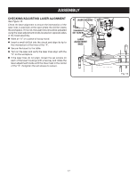
assembly CHECKING/adjusting Laser Alignment See Figure 15. Check the laser alignment to ensure the intersection of the laser lines is precisely at the spot where the drill bit meets the workpiece. If it is not, the laser lines should be adjusted using the laser adjustment knobs located on opposite sides of the head assembly. Mark an "X" on a piece of scrap wood. Insert a small drill bit into the chuck and align its tip to the intersection of the lines of the "X". Secure the board to the table. Turn on the laser and verify the laser lines align with the "X" on the workpiece. If the laser lines do not align, loosen the set screws on each of the laser housings with a hex key and rotate the laser adjustment knobs until the lines meet in the center of the "X". Retighten the set screws to secure. laser housing set screw LASER ADJUSTMENT knob Fig. 15 17
-
 1
1 -
2
-
3
-
4
-
5
-
6
-
7
-
8
-
9
-
10
-
11
-
 12
12 -
 13
13 -
 14
14 -
 15
15 -
 16
16 -
 17
17 -
 18
18 -
 19
19 -
 20
20 -
 21
21 -
 22
22 -
23
-
24
-
25
-
26
 |
 |
