Ryobi P4002 Operation Manual - Page 9
Operation
 |
View all Ryobi P4002 manuals
Add to My Manuals
Save this manual to your list of manuals |
Page 9 highlights
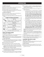
OPERATION INSTALLING/REMOVING POWER CORD See Figure 2, page 13. WARNING: Do not route cord under carpets, rugs, runners, furniture, or appliances and always route cord away from traffic areas to prevent a tripping hazard. Insert the female end of the power supply cord into the product as shown until it clicks into place. Connect the male end of the power cord to the power source. Make sure the power cord is secured before beginning operation. To remove the power cord, unplug the cord from the power source. Press the release button on the top of the female end of the power supply cord and remove from the tool. DIRECTION OF ROTATION SELECTOR (CLOCKWISE/COUNTERCLOCKWISE/CENTER LOCK) See Figure 3, page 13. Set the direction of rotation selector in the OFF (center lock) position to lock the switch trigger and help prevent accidental starting when not in use. Position the direction of rotation selector to the left of the switch trigger in the F/R (forward/retract) position to rotate the cable clockwise. Position the selector to the right of the switch trigger in the N (neutral) position to rotate the cable counterclockwise. NOTE: The tool will not run unless the direction of rotation selector is pushed fully to the left or right. NOTE: For optimal performance, position both the direction of rotation selector and the direction of feed collar as described later in the Feed and Rotation Chart. NOTICE: To prevent gear damage, always allow the cable to come to a complete stop before changing the direction of rotation. VARIABLE SPEED SWITCH TRIGGER See Figure 4, page 14. The variable speed switch trigger delivers higher speed with increased trigger pressure and lower speed with decreased trigger pressure. To turn the tool ON, depress the switch trigger. To turn it OFF, release the switch trigger and allow the cable to come to a complete stop. FEED DIRECTION SELECTOR COLLAR See Figures 5 and 6, page 14. The drain auger has three operating modes: forward (F), neutral (N), and retract (R). In the forward (F) position, squeezing the switch trigger will rotate and advance the cable. When the tool is in retract (R) position, the cable will rotate and retract as the switch trigger is squeezed. If the drain auger is in neutral (N), the cable will not rotate, advance, or retract. NOTE: Never run the tool while the collar is pushed in and in the neutral (N) position. Doing so will cause the cable to kink. To switch between modes: Lock the switch trigger by placing the direction of rotation selector in OFF (center lock) position. Pull the feed direction selector collar away from the tool and rotate it until the feed indicator is pointing at your desired operating mode. Push the collar toward the drum until it clicks into place. NOTE: The drum will rotate in the same direction regardless of the direction of feed. NOTE: For optimal performance, position both the direction of rotation selector and the direction of feed collar as described later in the Feed and Rotation Chart. WARNING: Be careful when adjusting the feed direction selector collar, keep fingers and cord away from pinch points. Failure to heed this warning could result in fingers being pinched or the cord being damaged. WARNING: Hybrid tools are always in operating condition. Therefore, lock the switch trigger when not in use or carrying at your side, when installing or removing the battery pack, when connecting or disconnecting the power cord, and when manually advancing or retracting the cable. Failure to follow these instructions could result in serious personal injury. 9 - English
-
 1
1 -
2
-
3
-
 4
4 -
 5
5 -
 6
6 -
 7
7 -
 8
8 -
 9
9 -
 10
10 -
 11
11 -
 12
12 -
 13
13 -
 14
14 -
15
-
16
-
17
-
18
-
19
-
20
-
21
-
22
-
23
-
24
-
25
-
26
-
27
-
28
-
29
-
30
-
31
-
32
-
33
-
34
-
35
-
36
-
37
-
38
-
39
-
40
 |
 |