Ryobi TS1345L User Manual - Page 10
Know Your Compound Miter Saw, In. Blade, Amp Motor, Bevel Lock Knob, Carrying Handle, Detent
 |
View all Ryobi TS1345L manuals
Add to My Manuals
Save this manual to your list of manuals |
Page 10 highlights
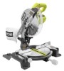
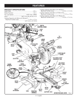
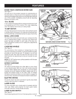
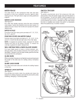
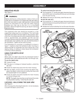
FEATURES KNOW YOUR COMPOUND MITER SAW See Figure 1. The safe use of this product requires an understanding of the information on the tool and in this operator's manual as well as a knowledge of the project you are attempting. Before use of this product, familiarize yourself with all operating features and safety rules. 10 in. BLADE A 10 in. blade is included with the compound miter saw. It will cut materials up to 3-1/2 in. thick or 12 in. wide, depending upon the angle at which the cut is being made. 15 AMP MOTOR The saw has a powerful 15 amp motor with sufficient power to handle tough cutting jobs. It is made with all ball bearings, and has externally accessible brushes for ease of servicing. BEVEL LOCK KNOB The bevel lock knob securely locks your compound miter saw at desired bevel angles. A positive stop adjustment screw has been provided on each side of the saw arm. These adjustment screws are for making fine adjustments at 0° and 45°. CARRYING HANDLE LASER GUIDE SWITCH LOCK PIN BEVEL LOCK KNOB "D" HANDLE SAW ARM LOCKED IN DOWN POSITION Fig. 2 CARRYING HANDLE See Figure 2. For convenience when carrying or transporting the miter saw from one place to another, a carrying handle has been provided on top of the saw arm. To transport, turn off and unplug the saw, then lower the saw arm and lock it in the down position by depressing the lock pin towards the saw housing. NOTE: DO NOT perform any cutting operation with the saw in the locked position. DETENT OVERRIDE See Figure 3. The detent override allows the miter table to move freely to any desired angle. With the miter lock handle loosened and the detent release lever squeezed (1), pull the detent override up (2) and release the detent release lever (3) to bypass the positive stops on the miter scale. To release the detent override and allow the miter table to engage the positive stops, squeeze and release the detent release lever. MITER LOCK HANDLE DETENT RELEASE LEVER DETENT OVERRIDE ELECTRIC BRAKE 3 An electric brake has been provided to quickly stop blade rotation after the switch is released. LASER GUIDE 1 2 For more accurate cuts, a laser guide is included with the miter saw. When used properly, the laser guide makes accurate, precision cutting simple and easy. LASER GUIDE SWITCH See Figure 2. Use the laser guide switch to turn the laser guide on and off. 10 − English Fig. 3
-
 1
1 -
2
-
3
-
4
-
 5
5 -
 6
6 -
 7
7 -
 8
8 -
 9
9 -
 10
10 -
 11
11 -
 12
12 -
 13
13 -
 14
14 -
 15
15 -
16
-
17
-
18
-
19
-
20
-
21
-
22
-
23
-
24
-
25
-
26
-
27
-
28
-
29
-
30
-
31
-
32
-
33
-
34
-
35
-
36
-
37
-
38
-
39
-
40
-
41
-
42
-
43
-
44
-
45
-
46
-
47
-
48
-
49
-
50
-
51
-
52
-
53
-
54
-
55
-
56
-
57
-
58
-
59
-
60
-
61
-
62
-
63
-
64
-
65
-
66
-
67
-
68
-
69
-
70
-
71
-
72
-
73
-
74
-
75
-
76
-
77
-
78
-
79
-
80
-
81
-
82
-
83
-
84
-
85
-
86
-
87
-
88
-
89
-
90
-
91
-
92
-
93
-
94
-
95
-
96
-
97
-
98
-
99
-
100
-
101
-
102
-
103
-
104
-
105
-
106
-
107
-
108
 |
 |
