Ryobi TS1345L User Manual - Page 14
Mounting Holes, Warning, Using The Depth Stop, Locking / Unlocking The Saw Arm
 |
View all Ryobi TS1345L manuals
Add to My Manuals
Save this manual to your list of manuals |
Page 14 highlights
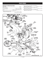
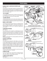
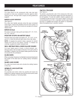
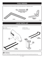
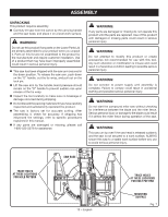
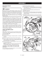
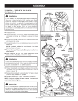
ASSEMBLY MOUNTING HOLES See Figure 7. WARNING: Before starting any cutting operation, clamp or bolt your miter saw to a workbench or an approved miter saw stand. If a miter saw stand is used, read operator's manual and follow the instructions for the miter saw stand. Never operate your miter saw on the floor or in a crouched position. Failure to heed this warning can result in serious personal injury. The compound miter saw should be mounted to a firm supporting surface such as a workbench. Four bolt holes have been provided in the saw base for this purpose. Each of the four mounting holes should be bolted securely using 5/16 in. machine bolts, lock washers, and hex nuts (not included). Bolts should be of sufficient length to accommodate the saw base, lock washers, hex nuts, and the thickness of the workbench. Tighten all four bolts securely. The hole pattern for mounting to a workbench is shown in figure 7. Carefully check the workbench after mounting to make sure that no movement can occur during use. If any tipping, sliding, or walking is noted, secure the workbench to the floor before operating. USING THE DEPTH STOP See Figure 8. When used, the depth stop limits the downward travel of the blade when cutting dadoes and other non-through cuts. To use the depth stop: Unplug the saw. If the saw is in storage or transport position, unlock the saw arm. Rotate the depth stop away from the motor housing. With the depth control knob touching the depth stop, adjust the depth control knob by turning the knob until the desired depth of cut is attained. Rotate the depth stop back towards the motor housing for normal through cuts. NOTE: The depth stop must be moved toward the motor housing before locking / unlocking the saw arm. LOCKING / UNLOCKING THE SAW ARM See Figure 9. When locking and unlocking the saw arm, it is not necessary to loosen the depth control knob. To unlock and raise the saw arm: Firmly grasp the "D" handle and apply downward pressure while at the same time pulling the lock pin out and away from the saw housing. Release the lock pin and slowly raise the saw arm. To lock the saw arm: Firmly grasp the "D" handle and apply downward pressure while at the same time pushing the lock pin in and toward the saw housing. Release the lock pin allowing it to lock the saw into place. DEPTH CONTROL KNOB "D" HANDLE DEPTH STOP Fig. 8 LOCK PIN Fig. 9 14 − English
-
 1
1 -
2
-
3
-
4
-
5
-
6
-
7
-
8
-
 9
9 -
 10
10 -
 11
11 -
 12
12 -
 13
13 -
 14
14 -
 15
15 -
 16
16 -
 17
17 -
 18
18 -
 19
19 -
20
-
21
-
22
-
23
-
24
-
25
-
26
-
27
-
28
-
29
-
30
-
31
-
32
-
33
-
34
-
35
-
36
-
37
-
38
-
39
-
40
-
41
-
42
-
43
-
44
-
45
-
46
-
47
-
48
-
49
-
50
-
51
-
52
-
53
-
54
-
55
-
56
-
57
-
58
-
59
-
60
-
61
-
62
-
63
-
64
-
65
-
66
-
67
-
68
-
69
-
70
-
71
-
72
-
73
-
74
-
75
-
76
-
77
-
78
-
79
-
80
-
81
-
82
-
83
-
84
-
85
-
86
-
87
-
88
-
89
-
90
-
91
-
92
-
93
-
94
-
95
-
96
-
97
-
98
-
99
-
100
-
101
-
102
-
103
-
104
-
105
-
106
-
107
-
108
 |
 |
