Ryobi TSS120L User Manual
Ryobi TSS120L Manual
 |
View all Ryobi TSS120L manuals
Add to My Manuals
Save this manual to your list of manuals |
Ryobi TSS120L manual content summary:
- Ryobi TSS120L | User Manual - Page 1
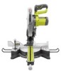
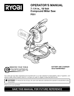
OPERATOR'S MANUAL 7-1/4 in., 18 Volt Compound Miter Saw P551 45 battery and charger sold separately Your miter saw has been engineered and manufactured to our high standard for dependability, ease of operation, and operator safety. When properly cared for, it will give you years of rugged, trouble- - Ryobi TSS120L | User Manual - Page 2
Rules...4-5 Symbols...6 Glossary of Terms...7 Features...8-10 Tools Needed...10 Loose Parts List...11 Assembly...12-19 Operation...20-27 Adjustments...28-29 Maintenance...30 Parts Ordering / Service...Back Page INTRODUCTION This tool has many features for making its use more - Ryobi TSS120L | User Manual - Page 3
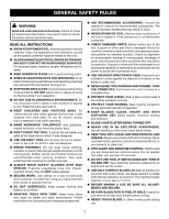
A guard or other part that is damaged must be properly repaired or replaced by an authorized service center to avoid risk of personal injury. USE THE RIGHT DIRECTION OF FEED. Feed work into a blade or cutter against the direction of rotation of the blade or cutter only. NEVER LEAVE TOOL RUNNING - Ryobi TSS120L | User Manual - Page 4
operate A tool while under the influence of drugs, alcohol, or any medication. When servicing use only identical replacement parts. Use of any other parts may create a hazard or cause product damage. DOUBLE CHECK ALL SETUPS. Make sure blade is tight and not making contact with saw or workpiece - Ryobi TSS120L | User Manual - Page 5
make sure you have good balance. NEVER operate your miter saw on the floor or in a crouched position. NEVER stand or have any part of your body in line with the path of the saw blade. ALWAYS release the power switch and allow the saw blade to stop rotating before raising it out of the workpiece - Ryobi TSS120L | User Manual - Page 6
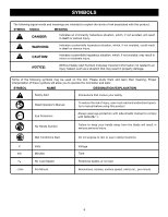
their meaning. Proper interpretation of these symbols will allow you to operate the tool better and safer. SYMBOL NAME DESIGNATION/EXPLANATION Safety Alert Precautions that involve your safety. Read Operator's Manual Eye Protection To reduce the risk of injury, user must read and understand - Ryobi TSS120L | User Manual - Page 7
a cut without the workpiece being guided by a fence, miter gauge, or other aids. Gum A sticky, sap-based residue from wood products. Heel Alignment of the blade to the fence. Kerf The material removed by the blade in a through cut or the slot produced by the blade in a non-through or partial - Ryobi TSS120L | User Manual - Page 8
in. x 3 in. Miter Lock lever BLADE WRENCH Dust BAG Upper Blade Guard "D" handle switch lock Switch Trigger laser guide Bevel Lock Knob Lower blade guard "NO HANDS ZONE" BOUNDARY LINE 45 30 33.9 15 0 1 2 3 4 5 "NO HANDS ZONE" LABEL bevel scale miter fence base 45 MITER TABLE WORK - Ryobi TSS120L | User Manual - Page 9
for the blade wrench is located in the saw's base. LASER GUIDE See Figure 2. For more accurate cuts, a laser guide is included with your miter saw. When used properly, the laser guide makes accurate, precision cutting simple and easy when the laser switch is turned on. MITER FENCE The miter fence on - Ryobi TSS120L | User Manual - Page 10
thumb then squeeze the switch trigger. To prevent unauthorized use of the compound miter saw, remove the battery pack, and lock the switch in the off position. Padlock TOOLS NEEDED 45 30 33.9 15 123 4 567 The following tools (not included) are needed for making adjustments or installing the blade: - Ryobi TSS120L | User Manual - Page 11
LOOSE PARTS LIST The following items are included with your compound miter saw: Dust Bag Rear Bracket/Carrying Handle Work Clamp Operator's Manual Blade Wrench DUST BAG WORK CLAMP blade wrench rear bracket/ carrying handle Fig. 6 WARNING: The use of attachments or accessories - Ryobi TSS120L | User Manual - Page 12
in this manual. If any parts are damaged or missing, please call 1-800-525-2579 for assistance. WARNING: Do not start the compound miter saw without checking for interference between the blade and the miter fence. Damage could result to the blade if it strikes the miter fence during operation - Ryobi TSS120L | User Manual - Page 13
ASSEMBLY WARNING: Always make sure the compound miter saw is securely mounted to a workbench or an approved workstand. Failure to heed this warning can result in serious personal injury. Mounting Holes See Figure 8. If not using a stand, the saw should be mounted to a firm supporting surface such - Ryobi TSS120L | User Manual - Page 14
ASSEMBLY WORK CLAMP See Figure 10. The work clamp provides greater control by clamping the workpiece to the fence. It also prevents the workpiece from creeping toward the saw blade. This is very helpful when cutting compound miters. Depending on the cutting operation and the size of the workpiece, - Ryobi TSS120L | User Manual - Page 15
and 4 ttio5gphrt6eenveS7nEtCgUuREaLrYd movement BLADE BOLT COVER SCREW Lower blade guard Fit saw blade inside lower blade guard and onto spindle. The blade teeth point downward at the front of saw as shown in figure 12. Replace outer blade washer. Double "D" flats on blade washers align with - Ryobi TSS120L | User Manual - Page 16
points being made in the illustrations. Never operate the saw without all guards securely in place and in good operating condition. SQUARING THE MITER TABLE TO THE FENCE See Figures 13 - 16. Remove the battery pack from the tool. Push down on the saw arm and pull out the lock pin to release the - Ryobi TSS120L | User Manual - Page 17
ASSEMBLY Socket Head Screw(s) Miter lock lever MITER FENCE 45 31.6 30 22.5 15 0 22.5 30 31.6 15 miter FENCE 45 Fig. 16 Blade MITER framing TABLE square VIEW OF Blade SQUARE WITH FENCE Fig. 17 SQUARING THE BLADE TO THE FENCE See Figures 16 - 19. Remove the battery pack from the tool - Ryobi TSS120L | User Manual - Page 18
ASSEMBLY SQUARING THE BLADE TO THE MITER TABLE See Figures 20 - 23. Remove the battery pack from the tool. Pull the saw arm all the way down and engage the lock pin to hold the saw arm in transport position. Lift the miter lock lever. Rotate the miter table until the pointer aligns with - Ryobi TSS120L | User Manual - Page 19
ASSEMBLY Danger: Laser radiation. Avoid direct eye contact with light source. WARNING: Use of controls or adjustments or performance of procedures other than those specified herein may result in hazardous radiation exposure. aligning the laser guide the mark with the blade at the uppermost position. - Ryobi TSS120L | User Manual - Page 20
the accessory blades available from the dealer. This product will accept Ryobi One+ 18 V lithium-ion battery packs and Ryobi One+ 18 V nickel-cadmium battery packs. For complete charging instructions, refer to the Operator's Manuals for your Ryobi One+ battery pack and charger models. WARNING: To - Ryobi TSS120L | User Manual - Page 21
against the fence, the board could collapse on the blade at the end of the cut, jamming the blade. When cutting long pieces of lumber or molding, support the opposite end of the stock with a roller stand or with a work surface level with the saw table. See Figure 32. 21 CROSS CUT 45 miter CUT - Ryobi TSS120L | User Manual - Page 22
of a board is placed against the fence, the board could collapse on the blade at the end of the cut, jamming the blade. When cutting long pieces of lumber or molding, support the opposite end of the stock with a roller stand or with a work surface level with the saw table. See Figure 32. Align - Ryobi TSS120L | User Manual - Page 23
speed. Slowly lower the blade into and through the workpiece. Release the switch trigger and allow the saw blade to stop rotating before raising the blade out of the workpiece. Wait until the blade stops before removing the workpiece from the miter table. to Compound Miter Cut See Figures 30 - Ryobi TSS120L | User Manual - Page 24
. Slowly lower the blade into and through the workpiece. Release the switch trigger and allow the saw blade to stop rotating before raising the blade out of the workpiece. Wait until the blade stops before removing the workpiece from the miter table. Long workpiece 0 45 Workpiece supports Fig - Ryobi TSS120L | User Manual - Page 25
B- 2.50° M- 29.62° B- 4.98° M- 29.15° B- 7.44° M- 28.48° B- 9.85° M- 27.62° B- 12.20° M- 26.57° B- 14.48° M- 25.31° B- 16.67° M- 23.86° B- 18.75° M- 22.21° B- 20 0.00° B- 18.00° Each B (Bevel) and M (Miter) Setting is Given to the Closest 0.005°. COMPOUND-ANGLE SETTINGS FOR POPULAR STRUCTURES 25 - Ryobi TSS120L | User Manual - Page 26
table using the compound features of the miter saw. 52° 38° ceiling w a l l Fence inside corner Top edge against fence = LEFT SIDE, INSIDE CORNER RIGHT SIDE, OUTSIDE CORNER MITER Table Fence outside corner BOTTOM edge against fence = RIGHT SIDE, INSIDE CORNER LEFT SIDE, OUTSIDE CORNER - Ryobi TSS120L | User Manual - Page 27
make sure it is positioned on the miter table with the convex side against the fence as shown in figure 34. If the blade near the completion of the cut. WARNING: To avoid a kickback and to avoid serious personal injury, never position the concave edge of bowed or warped material against the fence - Ryobi TSS120L | User Manual - Page 28
remove the battery pack from the tool when assembling parts. The compound miter saw has been adjusted at the factory tool. Loosen the bevel lock knob by turning the knob counterclockwise. Square the blade to the miter table as described in the Assembly section of this manual. If the blade - Ryobi TSS120L | User Manual - Page 29
the screw. NOTE: If laser does not align correctly, return to your nearest Ryobi Authorized Service Center for repair. To adjust the miter lock lever See Figure 38. Prior to squaring the saw blade to the fence, check and adjust the miter lock lever, if needed. In the "locked" position, the action of - Ryobi TSS120L | User Manual - Page 30
MAINTENANCE WARNING: When servicing, use only identical replacement parts. Use of any other parts may create a hazard or cause remove dirt, dust, oil, grease, etc. LUBRICATION All of the bearings in this tool are lubricated with a sufficient amount of high grade lubricant for the life of the unit - Ryobi TSS120L | User Manual - Page 31
NOTES 31 - Ryobi TSS120L | User Manual - Page 32
MANUAL 7-1/4 in., 18 Volt Cordless Compound Miter Saw P551 WARNING: This product and some dust created by power sanding, sawing list of Authorized Service Centers. • MODEL NO. AND SERIAL NO. The model number of this tool will be found on a plate attached to the motor housing. Please record the model
-
 1
1 -
 2
2 -
 3
3 -
 4
4 -
 5
5 -
 6
6 -
 7
7 -
8
-
9
-
10
-
11
-
12
-
13
-
14
-
15
-
16
-
17
-
18
-
19
-
20
-
21
-
22
-
23
-
24
-
25
-
26
-
27
-
28
-
29
-
30
-
31
-
32
 |
 |
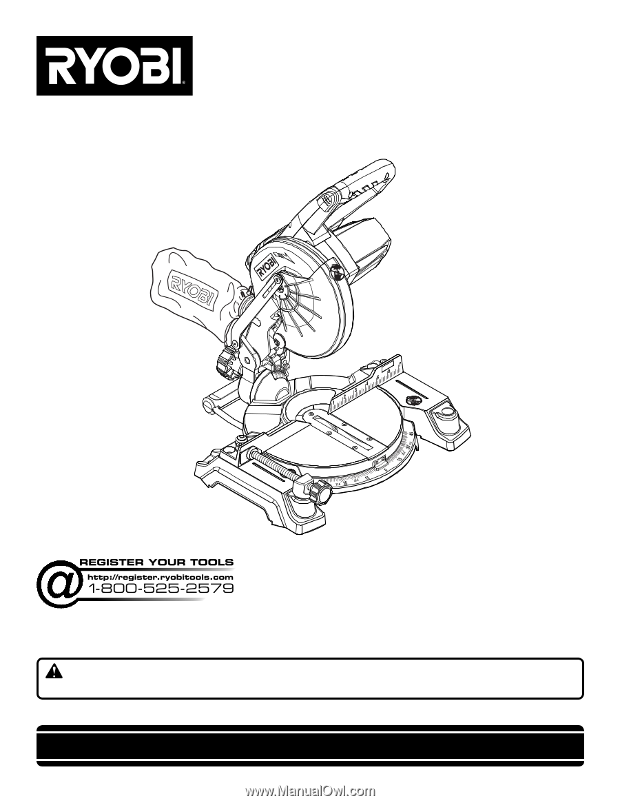
SAVE THIS MANUAL FOR FUTURE REFERENCE
Your miter saw has been engineered and manufactured to our high standard for dependability, ease of operation, and
operator safety. When properly cared for, it will give you years of rugged, trouble-free performance.
WARNING:
To reduce the risk of injury, the user must read and understand the operator’s manual before using
this product.
Thank you for your purchase.
OPERATOR’S MANUAL
7-1/4 in., 18 Volt
Compound Miter Saw
P551
45
BATTERY AND CHARGER
SOLD SEPARATELY