Ryobi TSS120L User Manual - Page 29
Danger, Warning, To Adjust The Laser Guide, To Adjust The Miter Lock Lever
 |
View all Ryobi TSS120L manuals
Add to My Manuals
Save this manual to your list of manuals |
Page 29 highlights
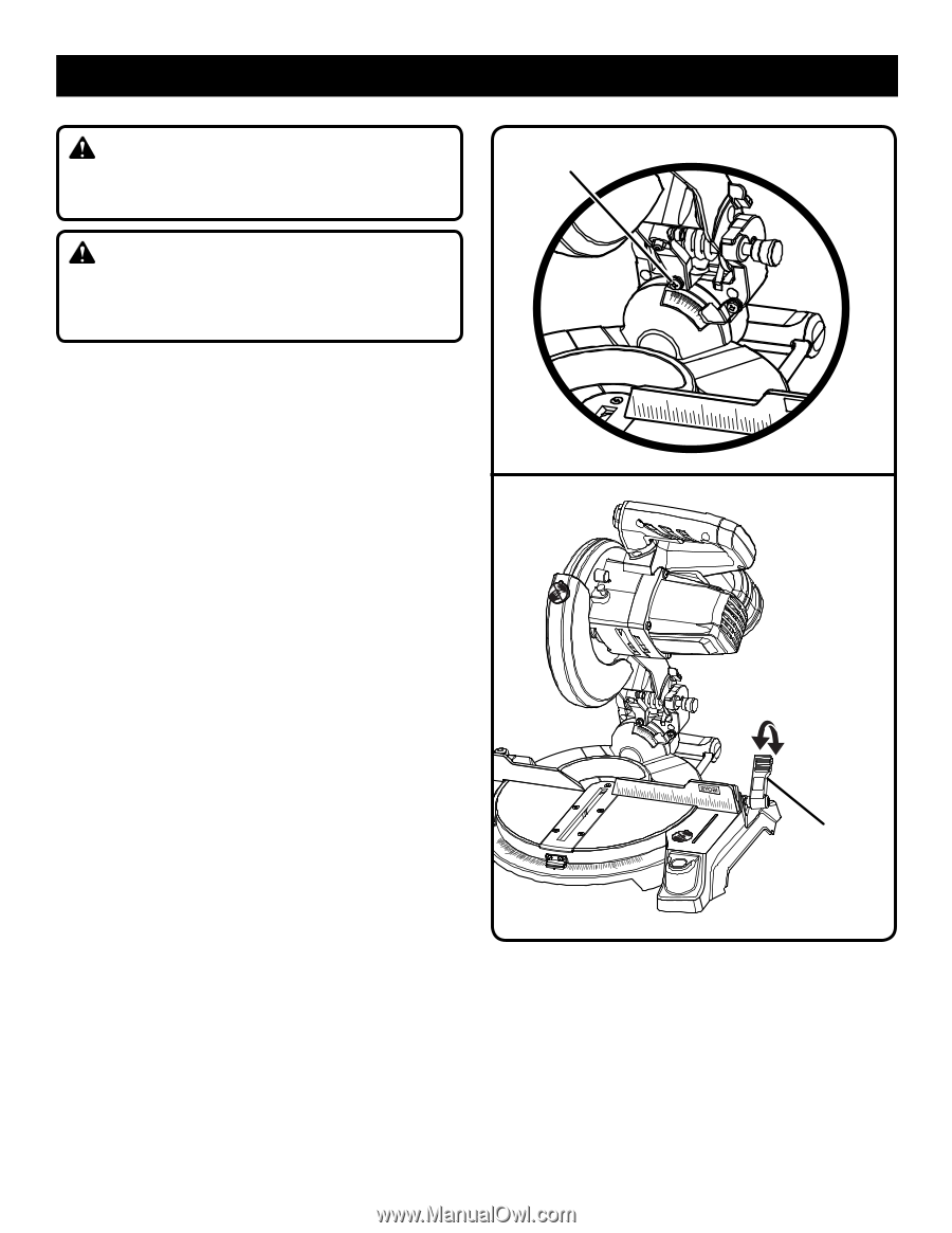
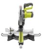
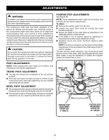
ADJUSTMENTS Danger: Laser radiation. Avoid direct eye contact with light source. laser adjustment screw WARNING: Use of controls or adjustments or performance of procedures other than those specified herein may result in hazardous radiation exposure. TO ADJUST THE LASER GUIDE See Figure 37. Set miter and bevel angles to 0º. Use the work clamp or a C-clamp to secure a piece of scrap wood. Turn the saw on and make a slight cut to score the wood. Release the switch trigger and allow the saw blade to stop rotating before raising the saw arm. Using a padlock, lock the switch trigger to make the saw inoperable. Turn on the laser switch. To adjust the laser, loosen the laser adjustment screw using the Phillips end of the supplied blade wrench. Move the laser left or right until properly aligned. NOTE: The laser should be on the left edge of the kerf. Once aligned, tighten the screw. NOTE: If laser does not align correctly, return to your nearest Ryobi Authorized Service Center for repair. To adjust the miter lock lever See Figure 38. Prior to squaring the saw blade to the fence, check and adjust the miter lock lever, if needed. In the "locked" position, the action of pushing the miter lock lever fully down should feel tight and secure. Considerable effort should be required to move the miter table. If the table moves easily when in the "locked" position, an adjustment of the miter lock lever is required. To adjust: Remove the battery pack from the tool. Push the miter lock lever fully down to lock. Pull the miter lock lever out to the right to disengage, then pull forward to adjust. Release miter lock lever to re-engage Recheck the miter table to ensure proper tightness. 0 0 45 45 30 33.9 15 1 2 3 4 5 Fig. 37 31.6 30 22.5 15 0 unlock 45 30 33.9 15 lock 1 2 3 4 5 6 7 45 15 22.5 30 31.6 miter lock lever Fig. 38 29
-
 1
1 -
2
-
3
-
4
-
5
-
6
-
7
-
8
-
9
-
10
-
11
-
12
-
13
-
14
-
15
-
16
-
17
-
18
-
19
-
20
-
21
-
22
-
23
-
 24
24 -
 25
25 -
 26
26 -
 27
27 -
 28
28 -
 29
29 -
 30
30 -
 31
31 -
 32
32
 |
 |