Ryobi WS750L Operation Manual - Page 10
Assembly
 |
View all Ryobi WS750L manuals
Add to My Manuals
Save this manual to your list of manuals |
Page 10 highlights
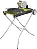
ASSEMBLY UNPACKING See Figure 5, page 20. This product requires assembly. Carefully lift the saw from the carton and place on a level work surface. WARNING: This new product has been shipped in a partially assembled condition as described below. Carefully check the packing list below to ensure all items are included in the package; the packing list describes all loose items that are not assembled to the product as shipped. Do not operate the product if any packing list items are already assembled to your product when you unpack it. Call the customer service number below for assistance. Operation of a product that may have been improperly preassembled could result in serious personal injury. Inspect the tool carefully to make sure no breakage or damage occurred during shipping. Do not discard the packing material until you ha ve carefully inspected and satisfactorily operated the tool. The saw is factory set for accurate cutting. After assembling it, check for accuracy. If shipping has influenced the settings, refer to specific procedures explained in this manual. If any parts are damaged or missing, please call 1-800-525-2579 for assistance. WARNING: If any parts are damaged or missing do not operate this tool until the parts are replaced. Failure to heed this warning could result in serious personal injury. WARNING: Do not attempt to modify this tool or create accessories not recommended for use with this tool. Any such alteration or modification is misuse and could result in a hazardous condition leading to possible serious personal injury. WARNING: Do not connect to power supply until assembly is complete. Failure to comply could result in accidental starting and possible serious personal injury. INSTALLING WHEELs See Figure 6a and 6b, page 21. Place the water tray frame on a flat, stable surface. Slide the axle through each of the holes on one end of the frame. Thread a sleeve and a large washer over one end of the axle. Insert the axle through the holes in section 1 of the leg stand. Slide a washer and a wheel over the axle. Slide a small washer over the axle. Insert a small bolt into the end of the axle. Tighten the bolt securely. Install the other wheel on the opposite side. ASSEMBLING THE LEG STAND See Figure 7, page 21. Leg sections 2 and 3 are pre-installed on the frame. Slide leg sections 2 and 3 along the frame so that they are positioned opposite the wheel end. Insert the H-bar leg section 6 into sections 2 and 3. The angled lower leg sections should be pointed outward and away from you. Working from the wheel end of the frame, insert leg section 4 into leg section 1 on the left side of the frame. Insert leg section 5 into leg section 1 on the right side of the frame. The angled lower legs (4 and 5) should be pointing outward and away from you. Insert a bolt through the square hole from the inside of leg section 2. Thread a spacer over the bolt, between the two legs. Insert the bolt through the holes in leg section 1. Thread a washer over the bolt. Secure the bolt with a nut and tighten securely. Repeat on the opposite side. Push down on the legs until the lock knob underneath the tray locks into place and the legs are secured. Make sure that all leg sections are securely tightened before turning the frame over to install the motor head assembly. NOTE: The ridged area on the end of the frame may be used as a handle for moving and transporting the saw. 10 - English
-
 1
1 -
2
-
3
-
4
-
 5
5 -
 6
6 -
 7
7 -
 8
8 -
 9
9 -
 10
10 -
 11
11 -
 12
12 -
 13
13 -
 14
14 -
 15
15 -
16
-
17
-
18
-
19
-
20
-
21
-
22
-
23
-
24
-
25
-
26
-
27
-
28
-
29
-
30
-
31
-
32
-
33
-
34
-
35
-
36
-
37
-
38
-
39
-
40
-
41
-
42
-
43
-
44
-
45
-
46
-
47
-
48
-
49
-
50
-
51
-
52
-
53
-
54
-
55
-
56
-
57
-
58
-
59
-
60
 |
 |
