Ryobi WS750L Operation Manual - Page 16
Adjustments - saw
 |
View all Ryobi WS750L manuals
Add to My Manuals
Save this manual to your list of manuals |
Page 16 highlights
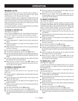
ADJUSTMENTS WARNING: Before performing any adjustment, make sure the tool is unplugged from the power supply and the switch is in the OFF position. Failure to heed this warning could result in serious personal injury. The saw has been adjusted at the factory for making very accurate cuts. However, some of the components might have been jarred out of alignment during shipping. Also, over a period of time, readjustment will probably become necessary due to wear. Do not start any adjustments until you have checked with a square and made test cuts to be sure adjustments are needed. To square the cutting wheel to the TABLE See Figure 32, page 26. Do not loosen any screws for this adjustment until you have checked with a square and made test cuts to be sure adjustments are necessary. Once the screws are loosened, these items must be reset. Unplug the saw. Using a 13 mm wrench or adjustable wrench (not included), loosen the hex bolt at the front of the frame and end of the slide rod. Move the table until the fence is square with the cutting wheel. Tighten the hex bolt securely. To ADJUST THE TABLE ROLLERS See Figure 33, page 26 If the table doesn't slide smoothly, seems too loose on the slide rod, or moves side to side, adjustments may be required. There are two different sets of shafts that may require adjustment. To adjust if the table is loose: Using a hex key and wrench (not included), loosen the bottom two shafts. These lower shafts can be adjusted up and down on the slide rod. If the table still doesn't slide smoothly, loosen the top two shafts. Once the rollers are sliding satisfactorily, tighten the screws securely. To adjust if the rollers are too tight: From the side closest to the frame, insert a hex key in the shaft. Holding the hex key to keep the shaft from turning, loosen the nylock nuts until the table slides at the desired smoothness. CAUTION: Use of controls or adjustments or performance of procedures other than those specified herein may result in hazardous radiation exposure. TO ADJUST THE LASER GUIDE See Figure 34, page 27. NOTE: Avoid direct eye exposure when using the laser guide. Unplug the saw. Using a marker or grease pencil, mark the material for a straight 90º cut. Place the material on the table and firmly against the rip guide and fence. Turn the laser on. Loosen the wheel guard lock and open the wheel guard. To adjust the laser line, loosen the Phillips head screw, adjust the laser module as needed, and tighten the screw securely. Once aligned, close and lock the wheel guard. NOTE: Always make practice cuts on scrap material before cutting through your workpiece. 16 - English
-
 1
1 -
2
-
3
-
4
-
5
-
6
-
7
-
8
-
9
-
10
-
 11
11 -
 12
12 -
 13
13 -
 14
14 -
 15
15 -
 16
16 -
 17
17 -
 18
18 -
 19
19 -
 20
20 -
 21
21 -
22
-
23
-
24
-
25
-
26
-
27
-
28
-
29
-
30
-
31
-
32
-
33
-
34
-
35
-
36
-
37
-
38
-
39
-
40
-
41
-
42
-
43
-
44
-
45
-
46
-
47
-
48
-
49
-
50
-
51
-
52
-
53
-
54
-
55
-
56
-
57
-
58
-
59
-
60
 |
 |
