Ryobi WS750L Operation Manual - Page 11
Inner Arm Cover To Frame - tile saw valve
 |
View all Ryobi WS750L manuals
Add to My Manuals
Save this manual to your list of manuals |
Page 11 highlights
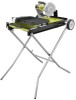
ASSEMBLY Installing motor head ASSEMBLY and inner arm cover to frame See Figure 8, page 21. Align the holes in the support arm with the holes on the side of the water tray frame. Insert large and small socket head screws and finger tighten. Using the hex key, securely tighten the large socket head screws on the side of the water tray frame. Tighten the small socket head screw last. Attach the inner arm cover as shown. Make sure the tab fits into the slot and the clear hose is centered in place so that water flow will not be restricted. Tighten the screws to hold it securely in place. INSTALLing the laser batteries See Figure 9, page 21. Using a Phillips screwdriver, remove the screw on the laser guide battery compartment cover. Install two AAA batteries, aligning the positives (+) with positives (+) and the negatives (-) with negatives (-) as shown inside the laser compartment. Replace the battery compartment cover and tighten the screw. Installing spLASH GUARD See Figure 10, page 22. Align the hole in the splash guard with the hole in the back of the motor head assembly. Using the flat washer and screw with Loctite®, secure the splash guard in place. Installing eND-of-cUT rEMINDER See Figure 11, page 22. The end-of-cut reminder slows down the Easy Glide Table™ to help prevent tile from cracking and chipping. Align the hole in the end-of-cut reminder with the hole in the back of the water tray frame. Using a screw, secure the end-of-cut reminder in place. Installing water tray See Figure 12, page 22. Slide the water tray into the frame from the front end of the saw. The hose connections and Clean Wave Wall™ should be positioned at the rear end of the saw. The saw may be operated using a garden hose for a continual fresh water supply, or the included pump may be used to recirculate the water in the tray. Installing THE PUMP See Figure 13 - 14, page 22 The pump is equipped with suction feet to hold it in place. Press down firmly on the pump to attach the feet to the Clean Wave Wall™ compartment of the water tray. Pull the water tray out slightly and feed the pump power cord through the slot in the back of the tray. Secure the power cord in the cord retainer. Connect the clear hose to the barbed end of the 90° fitting. Postion the pump as shown in Figure 13, with the hose end of the fitting facing the rear of the tray. Connect the plug for the pump to the power receptacle. After plugging the pump into the receptacle, pull the water guard over the connection. Push the water tray back into operating position before filling the tray or operating the saw. CONNECTING THE garden hose See Figure 15, page 23. The water supply must come from a fresh water main. NEVER turn the water supply on high. The water supply valve provides a convenient on/off for starting, stopping, and adjusting the water flow onto the cutting wheel. When used properly, the water supply valve adjusts the water flow to the perfect, optimal rate. Uncoil the garden hose. With the water main faucet turned completely off, attach the end of the garden hose to the water supply valve. Tighten by hand. Attach the clear hose into the water supply valve connection on the inside of the water tray. tile cutting wheel For maximum performance and safety, it is recommended that you use the 7 in. cutting wheel provided with the saw. Additional cutting wheels of the same high quality are available at your local dealer. WARNING: Do not use cutting wheels rated less than the no load speed of this tool. Failure to heed this warning could result in personal injury. Do not use wheel with cracks, gaps, or teeth. WARNING: To prevent possible electrical hazards, have a qualified electrician check the line if you are not certain that it is properly wired. 11 - English
-
 1
1 -
2
-
3
-
4
-
5
-
 6
6 -
 7
7 -
 8
8 -
 9
9 -
 10
10 -
 11
11 -
 12
12 -
 13
13 -
 14
14 -
 15
15 -
 16
16 -
17
-
18
-
19
-
20
-
21
-
22
-
23
-
24
-
25
-
26
-
27
-
28
-
29
-
30
-
31
-
32
-
33
-
34
-
35
-
36
-
37
-
38
-
39
-
40
-
41
-
42
-
43
-
44
-
45
-
46
-
47
-
48
-
49
-
50
-
51
-
52
-
53
-
54
-
55
-
56
-
57
-
58
-
59
-
60
 |
 |
