Samsung HC-P4741W User Manual (user Manual) (ver.1.0) (English) - Page 16
Connecting a Digital TV Set-Top Box, Connecting to Y, P
 |
View all Samsung HC-P4741W manuals
Add to My Manuals
Save this manual to your list of manuals |
Page 16 highlights
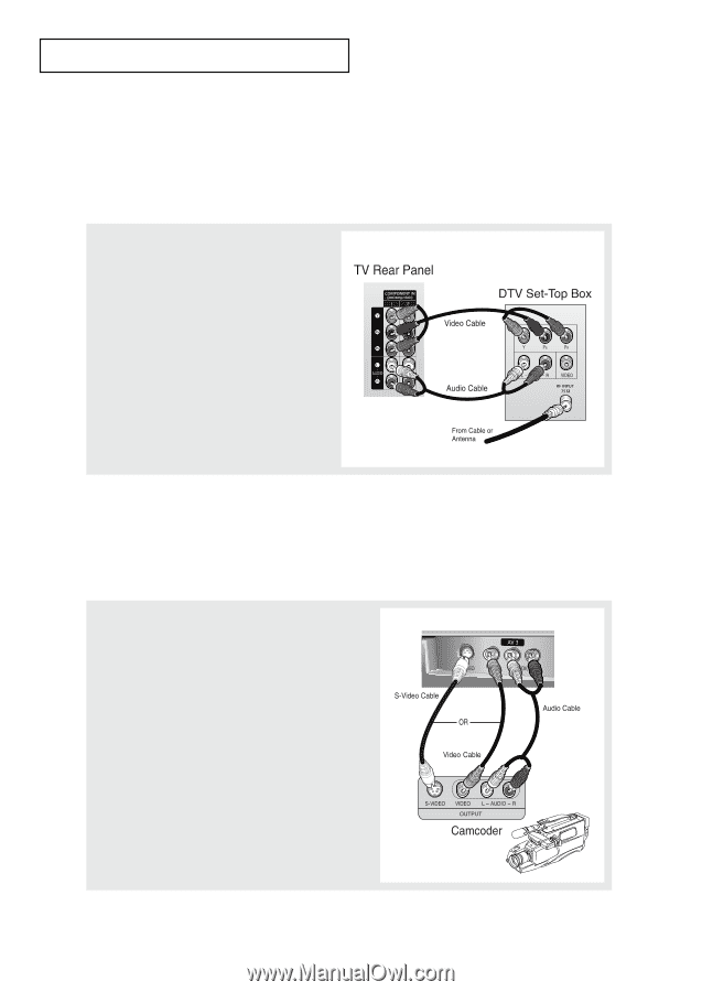
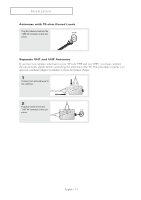
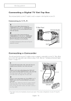
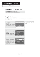
INSTALLATION Connecting a Digital TV Set-Top Box The rear panel jacks on your TV make it easy to connect a Set-Top Box to your TV. Connecting to Y, PB, PR 1 Connect a set of audio cables between the "COMPONENT IN 1 (L, R)" (or "COMPONENT IN 2 (L, R)") jacks on the TV and the AUDIO OUT jacks on the Set-Top Box. 2 Connect a set of video cables between the "COMPONENT IN 1 (Y, PB, PR)" (or "COMPONENT IN 2 (Y, PB, PR)") jacks on the TV and the VIDEO OUT (Y, PB, PR) jacks on the Set-Top Box. For detailed information, refer to the Set-Top Box instruction manual. Connecting a Camcorder The side panel jacks on your TV make it easy to connect a camcorder to your TV. They allow you to view the camcorder tapes without using a VCR. (Also see "Viewing an External Signal Source" on page 37.) 1 Locate the A/V output jacks on the camcorder. They are usually found on the side or rear of the camcorder. 2 Connect a set of audio cables between the "AV 3 (L, R)" jacks on the TV and the AUDIO OUT jacks on the camcorder. If you have mono camcorder, connect L(mono) to camcorder audio out using only one audio cable. 3 Connect a video cable between the "AV 3 (VIDEO)" (or "SVIDEO") jack on the TV and the VIDEO OUT jacks on the camcorder. The audio-video cables shown here are usually included with a Camcorder. (If not, check your local electronics store.) If your camcorder is stereo, you need to connect a set of two cables. TV Side Panel (HC-P4241W) • This figure shows the Standard connector-jack panel. The actual configuration for your TV may be different. English - 16
-
 1
1 -
2
-
3
-
4
-
5
-
6
-
7
-
8
-
9
-
10
-
 11
11 -
 12
12 -
 13
13 -
 14
14 -
 15
15 -
 16
16 -
 17
17 -
 18
18 -
 19
19 -
 20
20 -
 21
21 -
22
-
23
-
24
-
25
-
26
-
27
-
28
-
29
-
30
-
31
-
32
-
33
-
34
-
35
-
36
-
37
-
38
-
39
-
40
-
41
-
42
-
43
-
44
-
45
-
46
-
47
-
48
-
49
-
50
-
51
-
52
-
53
-
54
-
55
-
56
-
57
-
58
-
59
 |
 |