Samsung TX-S3082WH User Manual (user Manual) (ver.1.0) (English) - Page 11
Connecting a Second VCR to Record from the TV, Connecting a Camcorder
 |
View all Samsung TX-S3082WH manuals
Add to My Manuals
Save this manual to your list of manuals |
Page 11 highlights
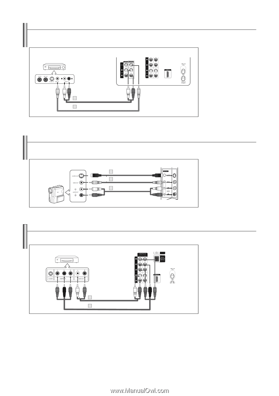
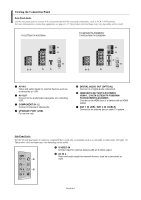
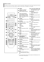
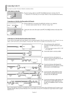
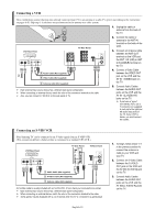
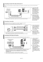
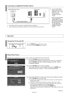
Connecting a Second VCR to Record from the TV Your TV can send out signals of its picture and sound to be recorded by a second VCR. To do this, connect your second VCR as follows: VCR Rear Panel TV Rear Panel 1. Connect a video cable between the AV OUT [VIDEO] jack on the TV and the VIDEO IN jack on the VCR. Refer to your VCR's instructions for more information about how to record using this kind of connection. 2 Audio Cable (Not supplied) 1 Video Cable (Not supplied) ➢ When connecting an external device, match the color of the connection terminal to the cable. 2. Connect a set of audio cables between the AV OUT [L-AUDIO-R] jacks on the TV and the AUDIO IN jacks on the VCR. (The VCR input jacks might be either on the front or on back of the VCR.) Connecting a Camcorder The side panel jacks on your TV make it easy to connect a camcorder to your TV. They allow you to view the camcorder tapes without using a VCR. Camcorder 1 S-Video Cable (Not supplied) or 1 Video Cable (Not supplied) 2 Audio Cable (Not supplied) TV Side Panel ➢ Each external input source device has a different back panel configuration. ➢ When connecting an external device, match the color of the connection terminal to the cable. Connecting a DVD Player/Set-Top Box 1. Connect a Video Cable (or S-Video Cable) between the AV IN2 [VIDEO] (or SVIDEO) jack on the TV and the VIDEO OUT jack on the camcorder. 2. Connect Audio Cables between the AV IN2 [LAUDIO-R] jacks on the TV and the AUDIO OUT jacks on the camcorder. The rear panel jacks on your TV make it easy to connect a DVD player/Set-Top Box to your TV. DVD Player/Set-Top Box TV Rear Panel 2 Audio Cable (Not supplied) 1 Component Cable (Not supplied) ➢ Component video separates the video into Y (Luminance (brightness)), PB (Blue) and PR (Red) for enhanced video quality. Be sure to match the component video and audio connections. For example, if connecting the video cable to COMPONENT IN, connect the audio cable to COMPONENT IN also. ➢ Each external input source device has a different back panel configuration. ➢ When connecting an external device, match the color of the connection terminal to the cable. 1. Connect a Component Cable between the COMPONENT IN 1 [Y, PB, PR](or COMPONENT IN 2 [Y, PB, PR]) jacks on the TV and the COMPONENT Y, PB, PR jacks on the DVD Player/Set-Top Box. 2. Connect Audio Cables between the COMPONENT IN 1 [L-AUDIO-R](or COMPONENT IN 2 [LAUDIO-R]) jacks on the TV and the AUDIO OUT jacks on the DVD Player/Set-Top Box. English-11
-
 1
1 -
2
-
3
-
4
-
5
-
 6
6 -
 7
7 -
 8
8 -
 9
9 -
 10
10 -
 11
11 -
 12
12 -
 13
13 -
 14
14 -
 15
15 -
 16
16 -
17
-
18
-
19
-
20
-
21
-
22
-
23
-
24
-
25
-
26
-
27
-
28
-
29
-
30
-
31
-
32
-
33
-
34
-
35
-
36
-
37
-
38
-
39
-
40
-
41
-
42
-
43
-
44
-
45
-
46
-
47
-
48
-
49
-
50
-
51
-
52
 |
 |