Sanyo PLC XU115 Instruction Manual, PLC-XU115 - Page 11
Rear Terminal, COMPUTER/COMPONENT AUDIO - projector service manual
 |
UPC - 086483071393
View all Sanyo PLC XU115 manuals
Add to My Manuals
Save this manual to your list of manuals |
Page 11 highlights
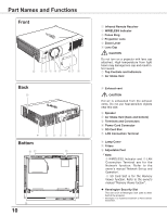
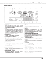
Rear Terminal ① ②③ ④ ⑤ Part Names and Functions ⑥ ⑦ SD ⑧ ⑨ ⑩ ⑪ ⑫ ⑬⑭ ① R/C JACK When using the wired remote control, connect the wired remote control to this jack with a remote control cable (not supplied). ② USB In order to operate the computer with the remote control and use the PAGE ▲▼ buttons on the remote control during a presentation, connect the USB port of the computer to the USB terminal with a USB cable (not supplied) (pp.13, 19). ③ SERVICE PORT This jack is used to service the projector. ④ COMPUTER IN 2/COMPONENT IN Connect the computer or component video (or RGB Scart) output signal to this terminal (pp.19, 21). Use the supplied VGA cable or a Component-VGA cable commercially available. ⑤ MONITOR OUT This terminal can be used to output the incoming RGB analog signal from COMPUTER IN 1 and COMPUTER IN 2/COMPONENT IN terminal to the other monitor (p.19). ⑥ COMPUTER IN 1/DVI-I Connect computer output (Digital/Analog DVI-I type) to this terminal (p.19). ⑦ LAN Connection Terminal Connect the LAN cable (Refer to the owner's manual of "Network Set-up and Operation".). ⑧ VIDEO IN Connect the composite video output signal to this jack (p.20). ⑨ AUDIO IN Connect the audio output signal from video equipment connected to ⑧ or ⑫ to this jack. For a mono audio signal (a single audio jack), connect it to the L (MONO) jack (p.20). ⑩ COMPUTER/COMPONENT AUDIO IN Connect the audio output (stereo) signal from a computer or video equipment connected to ④ or ⑥ to this jack (pp.19, 21). ⑪ AUDIO OUT (VARIABLE) Connect an external audio amplifier to this jack (pp.19-21). This terminal outputs sound from AUDIO IN terminal ( ⑨ or ⑩ ). ⑫ S-VIDEO IN Connect the S-VIDEO output signal from video equipment to this jack (p.20). ⑬ SD Card Indicator Display the status of SD card.When inserting SD Card, the indicator lights, and when removing SD Card, the indicator turns off. ⑭ SD Card Slot Insert the SD card memory (not supplied) for Memory viewer operation. 11
-
 1
1 -
2
-
3
-
4
-
5
-
 6
6 -
 7
7 -
 8
8 -
 9
9 -
 10
10 -
 11
11 -
 12
12 -
 13
13 -
 14
14 -
 15
15 -
 16
16 -
17
-
18
-
19
-
20
-
21
-
22
-
23
-
24
-
25
-
26
-
27
-
28
-
29
-
30
-
31
-
32
-
33
-
34
-
35
-
36
-
37
-
38
-
39
-
40
-
41
-
42
-
43
-
44
-
45
-
46
-
47
-
48
-
49
-
50
-
51
-
52
-
53
-
54
-
55
-
56
-
57
-
58
-
59
-
60
-
61
-
62
-
63
-
64
-
65
-
66
-
67
-
68
-
69
-
70
-
71
-
72
-
73
-
74
-
75
-
76
-
77
-
78
 |
 |
