Sanyo VCC-HD5600 VCC-HD5600 Setup and Summary Manual - Page 9
Outputting Alarm Signals OUT 1-2, Inputting Alarm Signals IN 1-8, Connecting the Controller 485A/
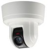 |
View all Sanyo VCC-HD5600 manuals
Add to My Manuals
Save this manual to your list of manuals |
Page 9 highlights
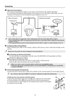
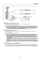
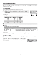
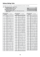
Connections COM ⁞ Alarm output signal OUT2 OUT1 C IN8 IN7 IN6 IN5 IN4 IN3 IN2 IN1 COM 485B 485A R D G R LL K OUT1/2 IN 1-8 Y B R R B O LL L WH S B COM Alarm input signal Controller connection White Yellow ⁞ Outputting Alarm Signals (OUT 1-2) Connect a buzzer, lamp, or other alarm device to the alarm output cable. Alarm can be output via two channels. • After connecting an alarm device, configure the output conditions for the corresponding alarm output terminal (ALARM OUT1 or 2) via network operation on the ALARM SETTINGS screen. • Configuration of alarm output terminal is also possible via remote operation. For that, set [ALARM OUT] to "REMOTE" on the ALARM SETTINGS screen. Inputting Alarm Signals (IN 1-8) Connect an alarm switch, infrared sensor, or other device to detect alarm conditions to the alarm input cable. Alarm can be input via eight channels. • After connecting an alarm device, configure the input conditions for the corresponding alarm input terminal (ALARM IN1 or 2) via network operation on the ALARM SETTINGS screen. • When using the alarm input terminal for day/night switching, configure the following settings. • Under [DAY/NIGHT], set [DAY/NIGHT] to "COLOR" and select the terminal you want to use in [EXT ALARM]. • On the ALARM SETTINGS screen, in [POLARITY], select the signal polarity of the alarm input terminal. • Connecting an external switch to ALARM IN1 allows you to set the system clock by operating the switch. To set the system clock, configure the [CLOCK IN] setting on the CLOCK SETTINGS screen. Connecting the Controller (485A/485B) By connecting a system controller (sold separately), the camera can be controlled remotely. Configure the protocol, baud rate and address. (Refer to "Control/Address Settings" Page 9.) 8
-
 1
1 -
2
-
3
-
 4
4 -
 5
5 -
 6
6 -
 7
7 -
 8
8 -
 9
9 -
 10
10 -
 11
11 -
 12
12 -
 13
13 -
 14
14 -
15
-
16
 |
 |
