Seagate Enterprise Capacity 3.5 HDD/Constellation ES Constellation ES (.1) SAS - Page 24
Hysical, Electrical Specifications
 |
View all Seagate Enterprise Capacity 3.5 HDD/Constellation ES manuals
Add to My Manuals
Save this manual to your list of manuals |
Page 24 highlights
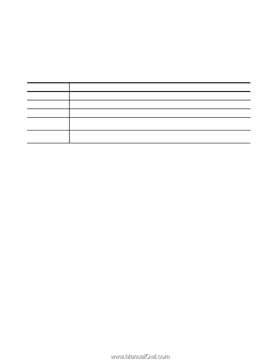
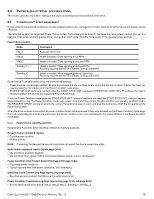
6.0 PHYSICAL/ELECTRICAL SPECIFICATIONS This section provides information relating to the physical and electrical characteristics of the drive. 6.1 POWERCHOICETM POWER MANAGEMENT Drives using the load/unload architecture provide programmable power management to tailor systems for performance and greater energy efficiency. The table below lists the supported PowerChoice modes. The further you go down in the table, the more power savings you get. For example, Idle2 mode results in greater power savings than Idle1 mode. Standby mode results in the greatest power savings. PowerChoice modes Mode Description Idle_A Reduced electronics Idle_B Heads unloaded. Disks spinning at full RPM Idle_C Heads unloaded. Disks spinning at reduced RPM Standby_Y Heads unloaded. Disks spinning at reduced RPM. Recovery requires the NOTIFY (Enable Spinup) command. Standby_Z Heads unloaded. Motor stopped (disks not spinning) Recovery requires the NOTIFY (Enable Spinup) command. PowerChoiceTM can be invoked using one of these two methods: • Power Condition mode page method-Enable and initialize the idle condition timers and/or the standby condition timers. The timer values are based on the values set in the Power Condition mode page. • START STOP UNIT command method-Use the START STOP UNIT command (OPERATION CODE 1Bh). This allows the host to directly transition the drive to any supported PowerChoice mode. If both the Power Condition mode page and START STOP UNIT command methods are used, the START STOP UNIT command request takes precedence over the Power Condition mode page power control and may disable the idle condition and standby condition timers. The REQUEST SENSE command reports the current PowerChoice state if active and also the method by which the drive entered the PowerChoice state. When the drive receives a command, all power condition timers are suspended if they were enabled via the Power Condition mode page. Once all outstanding commands are processed, the power condition timers are reinitialized to the values defined in the Power Condition mode page. 6.1.1 PowerChoice reporting methods PowerChoiceTM provides these reporting methods for tracking purposes: Request Sense command reports • Current power condition • Method of entry Note. Processing the Request Sense command does not impact the drive's power save state. Mode Sense command reports (mode page 0x1A) • Idle conditions enabled / disabled • Idle condition timer values (100ms increments) (default, saved, current, changeable) Power Condition Vital Product Data (VPD) Page (VPD page 0x8A) • Supported power conditions • Typical recovery time from power conditions (1ms increments) Start/Stop Cycle Counter Log Page reports (log page 0x0E) • Specified and accumulated Start/Stops and Load/Unload cycles Power Condition Transitions Log Page reports (log page 0x1A, subpage 0x00) • Accumulated transitions to Active, Idle_A, Idle_B, Idle_C, Standby_Y, Standby_Z CONSTELLATION ES.1 SAS PRODUCT MANUAL, REV. G 18
-
 1
1 -
2
-
3
-
4
-
5
-
6
-
7
-
8
-
9
-
10
-
11
-
12
-
13
-
14
-
15
-
16
-
17
-
18
-
 19
19 -
 20
20 -
 21
21 -
 22
22 -
 23
23 -
 24
24 -
 25
25 -
 26
26 -
 27
27 -
 28
28 -
 29
29 -
30
-
31
-
32
-
33
-
34
-
35
-
36
-
37
-
38
-
39
-
40
-
41
-
42
-
43
-
44
-
45
-
46
-
47
-
48
-
49
-
50
-
51
-
52
-
53
-
54
-
55
-
56
-
57
-
58
-
59
-
60
-
61
-
62
-
63
-
64
-
65
-
66
-
67
-
68
-
69
 |
 |