Seagate Enterprise Capacity 3.5 HDD/Constellation ES Constellation ES (.1) SAS - Page 27
Note.
 |
View all Seagate Enterprise Capacity 3.5 HDD/Constellation ES manuals
Add to My Manuals
Save this manual to your list of manuals |
Page 27 highlights
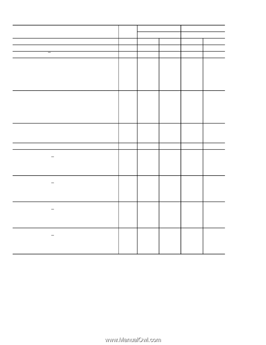
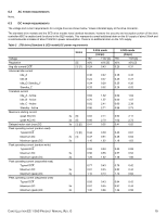
Table 4 500GB drive (Standard & SED model) DC power requirements Voltage Regulation Avg idle current DCX Advanced idle current Idle_A Idle_B Idle_C/ Standby_Y Standby_Z Transition current Idle_A - Active Idle_B - Active Idle_C - Active Standby - Active Maximum starting current (peak DC) DC (peak AC) AC Delayed motor start (max) DC Peak operating current (random read): Typical DCX Maximum DC Maximum (peak) DC Peak operating current (random write) Typical DCX Maximum DC Maximum (peak) DC Peak operating current (sequential read) Typical DCX Maximum DC Maximum (peak) DC Peak operating current (sequential write) Typical DCX Maximum DC Maximum (peak) DC Notes [5] [1] [7] 3.0Gb mode (Amps) +5V +12V [4] ±5% ±5% [2] 0.36 0.21 0.36 0.21 0.25 0.19 0.25 0.11 0.25 0.02 0.62 1.48 0.62 1.32 0.66 2.04 0.88 2.46 3s [5] 0.61 1.92 3s [5] 0.83 2.53 3s [1] [6] 0.44 0.02 [1] [6] 0.44 0.37 3s [1] 0.44 0.39 3s 1.18 1.48 0.54 0.28 3s 0.59 0.31 3s 1.32 1.47 0.77 0.20 3s 0.84 0.21 3s 1.07 0.40 0.95 0.20 3s 1.01 0.21 3s 1.40 0.38 6.0Gb mode (Amps) +5V +12V [4] ±5% ±5% [2] 0.36 0.21 0.36 0.21 0.25 0.19 0.25 0.12 0.26 0.02 0.64 1.42 0.70 1.35 0.84 2.05 0.86 2.53 0.61 1.93 0.96 2.59 0.44 0.02 0.44 0.38 0.50 0.41 1.29 1.45 0.54 0.29 0.59 0.41 1.32 1.47 0.77 0.20 0.84 0.21 1.07 0.43 0.95 0.20 1.01 0.21 1.38 0.38 Note. See table notes on the next page. [1] Measured with average reading DC ammeter. [2] Instantaneous +12V current peaks will exceed these values. [3] Power supply at nominal voltage. N (number of drives tested) = 6, 35 Degrees C ambient. [4] For +12 V, a -10% tolerance is allowed during initial spindle start but must return to ±5% before reaching 7200 RPM. The ±5% must be maintained after the drive signifies that its power-up sequence has been completed and that the drive is able to accept selection by the host initiator. [5] See +12V current profile in Figure 3. [6] This condition occurs after OOB and Speed Negotiation completes but before the drive has received the Notify Spinup primitive. [7] See paragraph 6.3.1, "Conducted noise immunity." Specified voltage tolerance includes ripple, noise, and transient response. [8] Operating condition is defined as random 8 block reads. [9] During idle, the drive heads are relocated every 60 seconds to a random location within the band from three-quarters to maximum track. CONSTELLATION ES.1 SAS PRODUCT MANUAL, REV. G 21
-
 1
1 -
2
-
3
-
4
-
5
-
6
-
7
-
8
-
9
-
10
-
11
-
12
-
13
-
14
-
15
-
16
-
17
-
18
-
19
-
20
-
21
-
 22
22 -
 23
23 -
 24
24 -
 25
25 -
 26
26 -
 27
27 -
 28
28 -
 29
29 -
 30
30 -
 31
31 -
 32
32 -
33
-
34
-
35
-
36
-
37
-
38
-
39
-
40
-
41
-
42
-
43
-
44
-
45
-
46
-
47
-
48
-
49
-
50
-
51
-
52
-
53
-
54
-
55
-
56
-
57
-
58
-
59
-
60
-
61
-
62
-
63
-
64
-
65
-
66
-
67
-
68
-
69
 |
 |