Seagate Enterprise Capacity 3.5 HDD/Constellation ES Constellation ES (.1) SAS - Page 6

Seagate Enterprise Capacity 3.5 HDD/Constellation ES Manual

Page 6 highlights

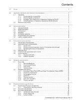
FIGURES Figure 1. Figure 2. Figure 3. Figure 4. Figure 5. Figure 6. Figure 7. Figure 8. Figure 9. Figure 10. Figure 11. Figure 12. Figure 13. Figure 14. Figure 15. Figure 16. Figure 17. Figure 18. Figure 19. 2TB model current profiles 22 1TB model current profiles 23 500GB model current profiles 24 2TB models (3Gb) DC current and power vs. input/output operations per second 25 2TB models (6Gb) DC current and power vs. input/output operations per second 26 1TB models (3Gb) DC current and power vs. input/output operations per second 27 1TB models (6Gb) DC current and power vs. input/output operations per second 28 500GB models (3Gb) DC current and power vs. input/output operations per second 29 500GB models (6Gb) DC current and power vs. input/output operations per second 30 Location of the HDA temperature check point 31 Recommended mounting 32 Mounting configuration dimensions 34 Example of FIPS tamper evidence labels 35 Physical interface 41 Air flow 42 Physical interface 53 SAS device plug dimensions 54 SAS device plug dimensions (detail 55 SAS transmitters and receivers 57 CONSTELLATION ES.1 SAS PRODUCT MANUAL, REV. G IV

  • 1
  • 2
  • 3
  • 4
  • 5
  • 6
  • 7
  • 8
  • 9
  • 10
  • 11
  • 12
  • 13
  • 14
  • 15
  • 16
  • 17
  • 18
  • 19
  • 20
  • 21
  • 22
  • 23
  • 24
  • 25
  • 26
  • 27
  • 28
  • 29
  • 30
  • 31
  • 32
  • 33
  • 34
  • 35
  • 36
  • 37
  • 38
  • 39
  • 40
  • 41
  • 42
  • 43
  • 44
  • 45
  • 46
  • 47
  • 48
  • 49
  • 50
  • 51
  • 52
  • 53
  • 54
  • 55
  • 56
  • 57
  • 58
  • 59
  • 60
  • 61
  • 62
  • 63
  • 64
  • 65
  • 66
  • 67
  • 68
  • 69

C
ONSTELLATION
ES.1 SAS P
RODUCT
M
ANUAL
, R
EV
. G
IV
F
IGURES
Figure 1.
2TB model current profiles
. . . . . . . . . . . . . . . . . . . . . . . . . . . . . . . . . . . . . . . . . . . . . . . . . . . 22
Figure 2.
1TB model current profiles . . . . . . . . . . . . . . . . . . . . . . . . . . . . . . . . . . . . . . . . . . . . . . . . . . . . 23
Figure 3.
500GB model current profiles . . . . . . . . . . . . . . . . . . . . . . . . . . . . . . . . . . . . . . . . . . . . . . . . .24
Figure 4.
2TB models (3Gb) DC current and power vs. input/output operations per second . . . . . . . . .25
Figure 5.
2TB models (6Gb) DC current and power vs. input/output operations per second . . . . . . . . .26
Figure 6.
1TB models (3Gb) DC current and power vs. input/output operations per second . . . . . . . . .27
Figure 7.
1TB models (6Gb) DC current and power vs. input/output operations per second . . . . . . . . .28
Figure 8.
500GB models (3Gb) DC current and power vs. input/output operations per second . . . . . . . 29
Figure 9.
500GB models (6Gb) DC current and power vs. input/output operations per second . . . . . . . 30
Figure 10.
Location of the HDA temperature check point . . . . . . . . . . . . . . . . . . . . . . . . . . . . . . . . . . . . . 31
Figure 11.
Recommended mounting . . . . . . . . . . . . . . . . . . . . . . . . . . . . . . . . . . . . . . . . . . . . . . . . . . . . . 32
Figure 12.
Mounting configuration dimensions . . . . . . . . . . . . . . . . . . . . . . . . . . . . . . . . . . . . . . . . . . . . . 34
Figure 13.
Example of FIPS tamper evidence labels. . . . . . . . . . . . . . . . . . . . . . . . . . . . . . . . . . . . . . . . . 35
Figure 14.
Physical interface . . . . . . . . . . . . . . . . . . . . . . . . . . . . . . . . . . . . . . . . . . . . . . . . . . . . . . . . . . . 41
Figure 15.
Air flow . . . . . . . . . . . . . . . . . . . . . . . . . . . . . . . . . . . . . . . . . . . . . . . . . . . . . . . . . . . . . . . . . . . 42
Figure 16.
Physical interface . . . . . . . . . . . . . . . . . . . . . . . . . . . . . . . . . . . . . . . . . . . . . . . . . . . . . . . . . . . 53
Figure 17.
SAS device plug dimensions . . . . . . . . . . . . . . . . . . . . . . . . . . . . . . . . . . . . . . . . . . . . . . . . . . 54
Figure 18.
SAS device plug dimensions (detail) . . . . . . . . . . . . . . . . . . . . . . . . . . . . . . . . . . . . . . . . . . . . 55
Figure 19.
SAS transmitters and receivers . . . . . . . . . . . . . . . . . . . . . . . . . . . . . . . . . . . . . . . . . . . . . . . . 57