Seagate ST160LT007 Momentus Thin (.2-4K) SATA Product Manual - Page 24
Configuring and mounting the drive
 |
View all Seagate ST160LT007 manuals
Add to My Manuals
Save this manual to your list of manuals |
Page 24 highlights
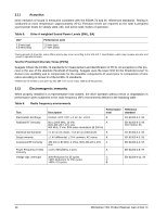
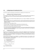
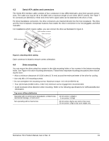
4.0 Configuring and mounting the drive This section contains the specifications and instructions for configuring and mounting the drive. 4.1 Handling and static-discharge precautions After unpacking, and before installation, the drive may be exposed to potential handling and electrostatic discharge (ESD) hazards. Observe the following standard handling and static-discharge precautions: Caution: • Keep the drive in the electrostatic discharge (ESD) bag until you are ready for installation to limit the drive's exposure to ESD. • Before handling the drive, put on a grounded wrist strap, or ground yourself frequently by touching the metal chassis of a computer that is plugged into a grounded outlet. Wear a grounded wrist strap throughout the entire installation procedure. • Handle the drive only by its edges or frame. • The drive is fragile-handle it with care. Do not press down on the drive top cover. • Always rest the drive on a padded, antistatic surface until you mount it in the computer. • Do not touch the connector pins or the printed circuit board. • Do not remove the factory-installed labels from the drive or cover them with additional labels. Removal voids the warranty. Some factory-installed labels contain information needed to service the drive. Other labels are used to seal out dirt and contamination. 4.2 Configuring the drive Each drive on the Serial ATA interface connects in a point-to-point configuration with the Serial ATA host adapter. There is no master/slave relationship because each drive is considered a master in a point-to-point relationships. If two drives are attached on one Serial ATA host adapter, the host operating system views the two devices as if they were both "masters" on two separate ports. This means both drives behave as if they are Device 0 (master) devices. Serial ATA drives are designed for easy installation. It is normally not necessary to set any jumpers on this drive for proper operation. If the host system does not support SATA 3Gb/s operation, place a jumper on pins 1 and 2 to limit the drive to 1.5Gb/s operation. 3.0 Gbits per second operation Limit data transfer rate to 1.5 Gbits per second Jumper block SATA power connector SATA interface connector Figure 2. Serial ATA connectors 18 Momentus Thin Product Manual, Gen-2 Rev. D
-
 1
1 -
2
-
3
-
4
-
5
-
6
-
7
-
8
-
9
-
10
-
11
-
12
-
13
-
14
-
15
-
16
-
17
-
18
-
 19
19 -
 20
20 -
 21
21 -
 22
22 -
 23
23 -
 24
24 -
 25
25 -
 26
26 -
 27
27 -
 28
28 -
 29
29 -
30
-
31
-
32
-
33
-
34
-
35
-
36
-
37
-
38
-
39
-
40
-
41
-
42
-
43
-
44
-
45
-
46
 |
 |