Sennheiser MEB 114 Instruction Manual SpeechLine Wired - Page 29
Connecting products via the logic function, Logic port, Function
 |
View all Sennheiser MEB 114 manuals
Add to My Manuals
Save this manual to your list of manuals |
Page 29 highlights
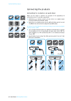
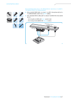
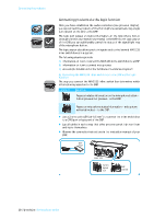
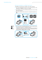
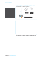
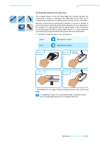
Connecting the products MEB 114-S MAT 133-S MAS 133 MAT 153-S MAS 133 Connecting products via the logic function Once you have established the audio connection (see previous chapter), you can connect the products of the IS microphone series featuring a logic port (shown on the left) to the DSP. The logic port passes on status information on the microphone button (microphone button pressed/not pressed) to the DSP. Via the logic output of the DSP, you can additionally control the status of the signal light ring of the microphone button. The logic output also allows you to integrate and control several MAS 133 inline switch boxes in a system. The following chapters provide A) information on how to connect the MAS 133 inline switch box to a DSP B) information on how to connect microphones C) an example installation for the Sennheiser TeamConnect system A) Connecting the MAS 133 inline switch box to the DSP via the logic function The way you connect the MAS 133 inline switch box determines which information is passed on to the DSP. Logic port Function Passes on status information on the microphone button - button pressed/not pressed- to the DSP. Passes on microphone status information - microphone activated/muted - to the DSP. ̈ Use a 2-wire cable (Ø 0.14-0.5 mm2) to connect the inline switch box to a GPIO port or logic port of the DSP. ̈ Lay all cables in such a way that other persons cannot trip over them and injure themselves. ̈ Observe the connection instructions in the instruction manual of your DSP. DSP logic MAS 133 Switch signal out DSP control 28 | SpeechLine IS microphone series
-
 1
1 -
2
-
3
-
4
-
5
-
6
-
7
-
8
-
9
-
10
-
11
-
12
-
13
-
14
-
15
-
16
-
17
-
18
-
19
-
20
-
21
-
22
-
23
-
 24
24 -
 25
25 -
 26
26 -
 27
27 -
 28
28 -
 29
29 -
 30
30 -
 31
31 -
 32
32 -
 33
33 -
 34
34 -
35
-
36
-
37
-
38
-
39
-
40
-
41
-
42
-
43
-
44
-
45
-
46
-
47
 |
 |
